Ford Escape 2020-2025 Owners Manual / Tire Sealant and Inflator Kit / Using the Tire Sealant and Inflator Kit / Tips for use of the kit. What to do when a tire is punctured
Ford Escape: Using the Tire Sealant and Inflator Kit / Tips for use of the kit. What to do when a tire is punctured
Tips for use of the kit
To ensure safe operation of the kit:
- Before operating the kit, make sure your vehicle is safely off the road and away from moving traffic.
- Do not remove any foreign objects, such as nails or screws, from the tire.
- Do not allow the compressor to operate continuously for more than 15 minutes. This will help prevent the compressor from overheating.
- Only use the kit when the ambient temperature is between -22°F (-30°C) and 158°F (70°C).
- Only use the sealing compound before the use-by date. The use-by date is on a label on the sealant canister and can be seen through the rectangular viewing window on the bottom of the compressor. Check the use-by date regularly and replace the canister when the sealant expires.
Note: Sealant compound contains latex. Use appropriate precautions to avoid any allergic reactions.
 When inflation only is required
for a tire or other objects, the
selector must be in the Air
position.
What to do when a tire is punctured
- A tire puncture within the tire's tread area can be repaired in two stages with the kit.
- In the first stage, the tire will be reinflated with a sealing compound and air. After the tire has been inflated, you will need to drive the vehicle a short distance approximately 4 mi (6 km) to distribute the sealant in the tire.
- In the second stage, you will need to check the tire pressure and adjust, if necessary, to the vehicle's specified tire inflation pressure.
 First Stage: Reinflating the Tire with sealing compound and air
WARNING: Do not stand directly
over the kit while inflating the tire. If you
notice any unusual bulges or
deformations in the tire's sidewall during
inflation, stop and call roadside
assistance...
Other information:
Ford Escape 2020-2025 Service Manual: Removal and Installation - Rear Stabilizer Bar Link
Removal NOTICE: Suspension fasteners are critical parts that affect the performance of vital components and systems. Failure of these fasteners may result in major service expense. Use the same or equivalent parts if replacement is necessary. Do not use a replacement part of lesser quality or substitute design...
Ford Escape 2020-2025 Service Manual: Description and Operation - Electric Powertrain Control - Component Location
Inverter System Controller Item Description 1 Inverter System Controller High Voltage Battery Coolant Temperature Sensor Item Description 1 High Voltage Battery Coolant Temperature Sensor ..
Categories
- Manuals Home
- 4th Generation Ford Escape Owners Manual
- 4th Generation Ford Escape Service Manual
- Switching the Lane Keeping System On and Off. Switching the Lane Keeping System Mode. Alert Mode
- Fuel Quality
- Plug-In Hybrid Electric Vehicle Drive Modes
- New on site
- Most important about car
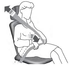
Adjusting the Seatbelts During Pregnancy
WARNING: Always ride and drive with your seatback upright and properly fasten your seatbelt. Fit the lap portion of the seatbelt snugly and low across the hips. Position the shoulder portion of the seatbelt across your chest. Pregnant women must follow this practice. See the following figure.

Copyright © 2025 www.fordescape4.com

