Ford Escape: Voltage Converter/Inverter / Description and Operation - Direct Current/Alternating Current (DC/AC) Inverter - System Operation and Component Description
System Diagram
.jpg)
System Operation
Network Message Chart
| Broadcast Message | Originating Module | Message Purpose |
| Power pack torque status | Secondary On-Board Diagnostic Control Module C (SOBDMC) | Used to determine if the vehicle is started or if torque is available. |
DC/AC INVERTER AND AC POWER POINT
The 110 volts AC created by the inverter measures differently than a conventional AC outlet (utility generated) with some multi-meters. The power point automatically shuts off if the load exceeds 150 watts to prevent damage to the inverter or load. The inverter supplies 110 volts AC power only when the ignition is ON. If the ignition is ON, but the vehicle is not started, the DC / AC inverter automatically shuts off after 13 minutes. The inverter can be powered back on and the timer reset by cycling the ignition from RUN to OFF and back to RUN, but only for another 13 minutes. This feature is intended to prevent the 12-volt battery from being fully discharged. If the vehicle is started (Ready indicator light ON), the inverter operation is not time-limited.
The DC / AC inverter time-out is controlled by a LIN circuit. The BCM transmits the vehicle status over the network to the DC / AC inverter. Once the DC / AC inverter stops receiving information that indicates the vehicle is started, it begins counting the amount of time the engine has not been running. If, after 13 minutes, the DC / AC inverter still has not received information that indicates the vehicle is started, the DC / AC inverter times out and stops supplying voltage to the AC power point.
The AC outlet is equipped with a LED that indicates the system status. The LED is illuminated continuously when the inverter is ON and the system is operating normally. When the inverter shuts off after 13 minutes, the LED flashes until the ignition is cycled. Additionally, the LED flashes constantly if the ignition is ON and a fault is detected.
The DC - AC inverter has a self-protection feature for the following conditions:
- Short circuits on the inverter output circuits: If the inverter detects a short on the output circuit(s), it shuts down. After 6 seconds, it restarts and checks for a short condition. If the condition still exists, the inverter shuts down again. The inverter restarts 5 times and, if the short still exists on the 5th restart the inverter disables AC output and flashes the LED indicator.
- Low voltage input: The inverter does not operate when the input voltage is less than 11 volts.
- High voltage input: The inverter does not operate when the input voltage is greater than 16 volts.
- Overload
- High temperature: The inverter does not operate if it has overheated or if ambient (cabin) temperatures exceed 75 C (167 F).
If the self-protection feature is activated, the LED indicator flashes and the DC - AC inverter does not provide power output to the AC outlet. If the LED is flashing, the problem must be corrected before DC - AC inverter operation will resume.
Refer to the Owner's Literature for a list of appropriate electrical loads/devices that can be used.
Component Description
COMPONENT OPERATION
The AC power outlet socket and inverter are replaced as separate components. The AC outlet is a standard 3-prong outlet, similar to a standard wall outlet. The contacts of the outlet exert a more powerful grip on the plug so that it does not shake loose on poor road surfaces.
 Diagnosis and Testing - Direct Current/Direct Current (DC/DC) Converter Control Module
Diagnostic Trouble Code (DTC) Chart
Diagnostics in this manual assume a certain skill level and knowledge of Ford-specific diagnostic practices. REFER to: Diagnostic Methods (100-00 General Information, Description and Operation)...
Other information:
Ford Escape 2020-2025 Service Manual: Removal and Installation - Brake Pedal and Bracket - Vehicles With: Electric Brake Booster
Removal NOTE: Removal steps in this procedure may contain installation details. Remove the cowl panel grille Refer to: Cowl Panel Grille (501-02 Front End Body Panels, Removal and Installation). Remove the 2 LH side (under hood) instrument panel bolts Torque: 35 lb...
Ford Escape 2020-2025 Service Manual: Removal and Installation - Rear Scuff Plate Trim Panel
Special Tool(s) / General Equipment Interior Trim Remover Removal NOTE: LH (left hand) shown, RH (right hand) similar. Release the clips and remove the rear scuff plate trim panel. Use the General Equipment: Interior Trim Remover Installation To install, reverse the removal procedure...
Categories
- Manuals Home
- 4th Generation Ford Escape Owners Manual
- 4th Generation Ford Escape Service Manual
- Rear View Camera
- Symbols Glossary
- Drive Modes
- New on site
- Most important about car
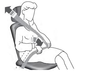
Adjusting the Seatbelts During Pregnancy
WARNING: Always ride and drive with your seatback upright and properly fasten your seatbelt. Fit the lap portion of the seatbelt snugly and low across the hips. Position the shoulder portion of the seatbelt across your chest. Pregnant women must follow this practice. See the following figure.


