Ford Escape: Hydraulic Brake Actuation / Removal and Installation - Brake Pedal and Bracket - Vehicles With: Electric Brake Booster
Removal
NOTE:
Removal steps in this procedure may contain installation details.
-
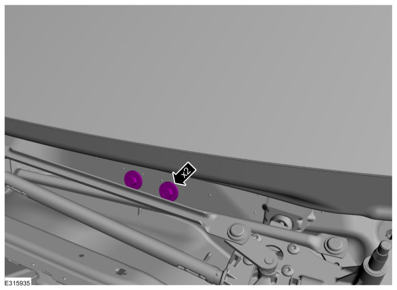
Remove the cowl panel grille
Refer to: Cowl Panel Grille (501-02 Front End Body Panels, Removal and Installation).
-
Remove the 2 LH side (under hood) instrument panel bolts
Torque:
35 lb.ft (48 Nm)
-
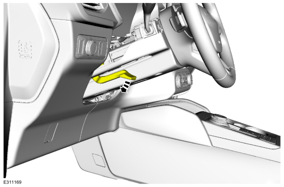
Position the manual steering column adjuster lever in the down position.
-
Remove the bolts and the lower steering column shroud.
Torque:
17 lb.in (1.9 Nm)
-
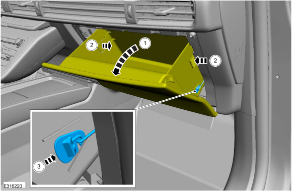
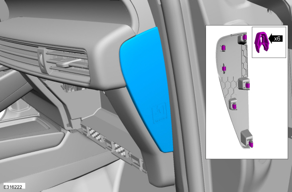
Release the clips and remove the LH instrument panel end cap.
-
-
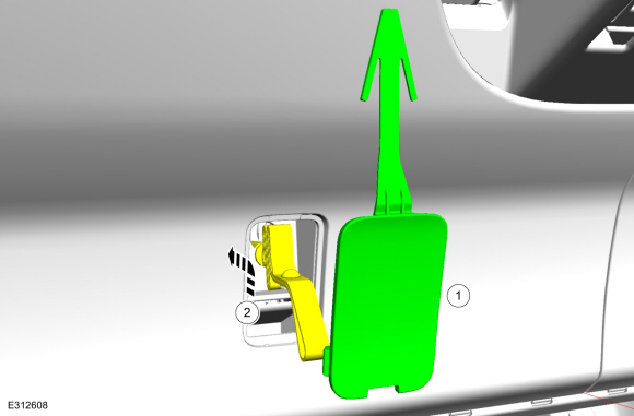
Remove the cover.
-
Lift the cable and strap upward and reward to disengage from the lower trim panel.
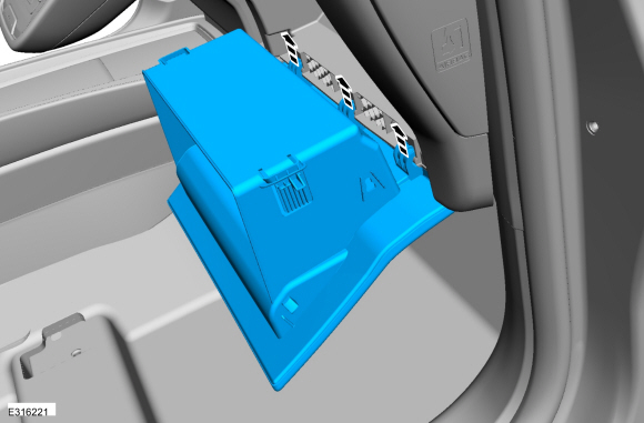
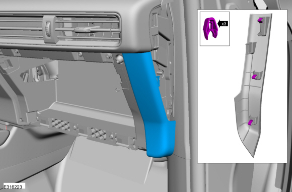
-
Release the clips and remove the LH trim panel.
-
Disconnect the electrical connector.
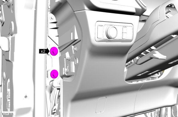
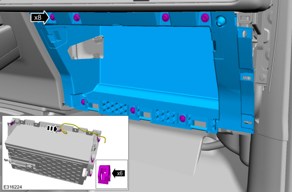
-
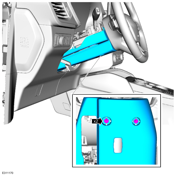
Remove the bolts.
Torque:
35 lb.ft (48 Nm)
-
Remove the accelerator pedal.
Refer to: Accelerator Pedal (310-02)
.
-
NOTICE:
Do not service the brake pedal or brake booster
without first removing the stoplamp switch. The switch must be removed
with the brake pedal in the at-rest position. The switch plunger must be
compressed for the switch to rotate in the bracket. Attempting to
remove the switch when the plunger is extended (during pedal apply) will
result in damage to the switch.
Remove the stoplamp switch.
Refer to: Stoplamp Switch (417-01 Exterior Lighting, Removal and Installation).
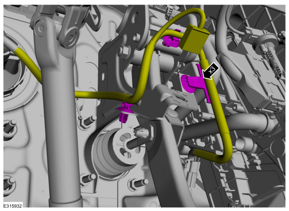
-
Detach the harness retainers and position the wiring aside.
-
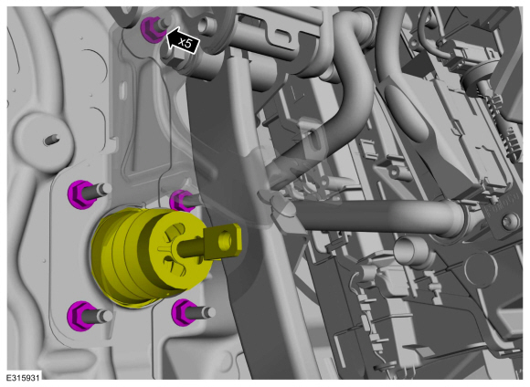
Remove and discard the clevis pin.
-
Remove the 5 brake pedal bracket nuts.
-
NOTE:
Have an assistant to pull the HCU away from the cowl enough to allow the brake pedal bracket to clear the studs.
-
Pull the LH side of the instrument panel away from the cowl slightly.
-
Remove the brake pedal and bracket.
Installation
-
NOTICE:
Do not press, pull or otherwise move the brake pedal
while installing the stoplamp switch. The switch must be installed with
the booster push rod attached to the brake pedal and with the brake
pedal in the at-rest position. Installing the switch with the brake
pedal in any other position will result in incorrect adjustment and may
damage the switch.
To install, reverse the removal procedure.
-
Install the 5 brake pedal bracket nuts in the sequence shown.
Torque:
18 lb.ft (25 Nm)
Removal
NOTE:
Removal steps in this procedure may contain installation details.
Remove the cowl panel grille
Refer to: Cowl Panel Grille (501-02 Front End Body Panels, Removal and Installation)...
Other information:
Removal
NOTE:
Removal steps in this procedure may contain installation details.
Lower the headliner.
Refer to: Headliner - Lowering (501-05 Interior Trim and Ornamentation, Removal and Installation).
Disconnect the electrical connector, release the tabs and remove the ANC microphone.
Installation
To install, reverse the removal procedur..
Removal
WARNING:
Do not smoke, carry lighted tobacco or have an open flame of
any type when working on or near any fuel-related component. Highly
flammable mixtures may be present and may be ignited. Failure to follow
these instructions may result in serious personal injury.
WARNING:
Do not carry personal electronic devices such as cell
phones, pagers or audio equipme..
 Removal and Installation - Brake Pedal and Bracket - Vehicles With: Vacuum Brake Booster
