Ford Escape: Interior Lighting / Description and Operation - Interior Lighting - Overview
Overview
The interior lighting system consists of:
- Courtesy lamps
- Demand lamps
- Ambient lighting
The courtesy lamps subsystem consists of:
- Interior overhead lamps
- Luggage compartment lamp
- Cargo lamp
- Courtesy lamp switch (integrated into the overhead console)
- Door ajar switches (integrated into the door latches)
- Liftgate ajar switch (integrated into the liftgate latch, manual liftgate)
- RGTM (power liftgate only)
- BCM
The courtesy lamps provide illumination to the vehicle interior, front scuff plates and below the exterior mirrors when entering or exiting the vehicle or when requested using the courtesy lamp switch located on the headlamp switch.
The demand lamps subsystem consists of:
- Interior overhead lamps (map lamps)
- Vanity mirror lamps
- Luggage compartment lamp
- Cargo lamp
- Media bin lamp
- BCM
The demand lamps provide illumination to specific areas within the vehicle when needed.
The BCM supplies voltage to the demand lamps when the battery saver feature is not active.
The ambient lighting subsystem consists of:
- Ambient lighting Light Emitting Diodes (LEDs)
- FDIM (touchscreen)
- BCM
The ambient lighting is controlled using the FDIM (touchscreen) controls. The ambient lighting provides aesthetically colored illumination to the following locations for illuminated entry or when the ignition is in RUN with the parking lamps on:
- Front console storage bin
- Front doors
- Front footwells
 Description and Operation - Interior Lighting - System Operation and Component Description
System Operation
System Diagram
Item
Description
1
LIN
2
Floor Console Storage Bin Lamp
3
Front Footwell Ambient Lighting LEDs
4
Door Ambient Lighting LEDs
5
LIN
6
HS-CAN1
7
APIM
8
HS-CAN3
9
FDIM
10
GWM
11
Headlamp Switch
12
Door Ajar Switches
13
without power liftg..
Other information:
Ford Escape 2020-2026 Owners Manual: All-Wheel Drive
How Does All-Wheel Drive Work All-wheel drive uses all four wheels to power the vehicle. This increases traction, enabling you to drive over terrain and road conditions that a conventional two-wheel drive vehicle cannot. The AWD system turns on when needed and does not require input from you. Note: The AWD feature gives your vehicle some limited off-road capabilities in which driving surfa..
Ford Escape 2020-2026 Service Manual: Diagnosis and Testing - Intake Air Pressure and Temperature
Diagnostic Trouble Code (DTC) Chart Diagnostics in this manual assume a certain skill level and knowledge of Ford-specific diagnostic practices.REFER to: Diagnostic Methods (100-00 General Information, Description and Operation). Module DTC Description Action PCM P007A:00 Charge Air Cooler Temperature Sensor Circuit (Bank 1): No Sub Type Information GO to Pinpoint Test DN P..
Categories
- Manuals Home
- 4th Generation Ford Escape Owners Manual
- 4th Generation Ford Escape Service Manual
- Description and Operation - Identification Codes
- Accessing the Trip Computer. Resetting the Trip Computer
- Fuel Quality
- New on site
- Most important about car
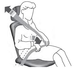
Adjusting the Seatbelts During Pregnancy
WARNING: Always ride and drive with your seatback upright and properly fasten your seatbelt. Fit the lap portion of the seatbelt snugly and low across the hips. Position the shoulder portion of the seatbelt across your chest. Pregnant women must follow this practice. See the following figure.


