Ford Escape: Automatic Transmission - Automatic Transmission – HF45 / Description and Operation - Transmission Description - System Operation and Component Description
System Diagram
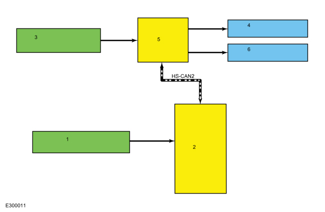
E357528 *.sttxt { visibility: hidden; } *.stcallout { visibility: visible; } 1 ABS 2 BECM 3 DC/DC 4 GWM 5 PCM 6 ISC 7 Transmission 8 Motor/Generator Speed Sensors 9 Motor/Generator Coil Temp Sensors 10 TFT Sensor 11 Park Lock Actuator 12 Field Coils| Item | Description |
|---|---|
| 1 | ABS |
| 2 | BECM |
| 3 | DCDC |
| 4 | GWM |
| 5 | PCM |
| 6 | ISC (inverter system controller) |
| 7 | Transmission |
| 8 | Motor/Generator Speed Sensors |
| 9 | Motor/Generator Coil Temp Sensors |
| 10 | TFT Sensor |
| 11 | Park Lock Actuator |
| 12 | Field Coils |
Network Message Chart
| Broadcast Message | Originating Module | Message Purpose |
|---|---|---|
| ABS fault | ABS module | Supplies ABS system fault status. |
| Battery available status | BECM | Supplies HV system charge status. |
| Battery charge limit | BECM | How much charge the high voltage battery can accept. |
| Battery power charge/discharge | BECM | How much power the high voltage battery can provide. |
| Battery state of charge limit | BECM | Hazard lamp/malfunction indicator lamp illumination request. |
| Battery temperature (HV) | BECM | Determines the battery temperature for the actual state of charge. |
| Brake pedal movement | ABS module | Supplies brake status information for regenerative braking. |
| Engine RPM | PCM | Calculates engine torque. |
| PHEV / FHEV engine data | PCM | Calculates engine torque. |
| Regenerative braking mode | ABS module | Indicates when the brakes are applied to switch to regenerative braking mode. |
System Operation
Component Description
Sensors and Actuators
| Item | Description |
|---|---|
| 1 | TFT sensor |
| 2 | Park lock actuator |
The TFT sensor is a thermistor located on the internal transmission harness. It sends a voltage signal to the ISC (inverter system controller). The voltage signal varies with TFT . The TFT sensor can not be serviced in vehicle, the transmission must be removed and disassembled.
The park lock actuator is an internally mounted actuator. The park lock actuator engages the park pawl with the park gear when commanded by the ISC. The park lock actuator cannot be serviced in vehicle, the transmission must be removed and disassembled. The PCM uses the park lock actuator signal for range selection, torque calculation and reverse lamp operation.
Park
.jpg)
| Item | Description |
|---|---|
| 1 | Park lock actuator |
| 2 | Park pawl |
| 3 | Park rod |
Power flow
In electric mode, torque flows from the electric motor to the transfer shaft and to the final drive ring gear. When the engine is off, the planetary carrier is held and the planetary ring gear is driven by the transfer shaft. This action causes the sun gear and the generator/starter to rotate. Under certain conditions, the SOBDMC will command the generator/starter to produce electricity for the electric motor and to charge the batteries.
Engine Starting Power flow
.jpg)
To start the engine, the final drive works as a holding element to the ring gear in the planetary assembly. The generator/starter turns the sun gear to start the engine.
Engine Charging Power flow
To charge the batteries, the final drive works as a holding element to the ring gear in the planetary assembly. The engine turns the carrier. This actions allows the generator/starter to produce current to charge the batteries and power the electric motor.
Regenerative Braking
When additional torque is needed to propel the vehicle, the generator/starter works as a holding element to the planetary sun gear. The flow of torque from the transfer shaft to the planetary ring gear is reversed and torque from the engine combines with the electric motor torque at the transfer shaft.
.jpg)

 Diagnosis and Testing - Automatic Transmission
Diagnostic Trouble Code (DTC) Chart
Diagnostics in this manual assume a certain skill level and knowledge of Ford-specific diagnostic practices. REFER to: Diagnostic Methods (100-00 General Information, Description and Operation)...
Other information:
Ford Escape 2020-2026 Service Manual: Removal and Installation - Front Door Speaker
Removal NOTE: Removal steps in this procedure may contain installation details. NOTE: LH front door speaker is shown, RH side front door speaker is similar. Remove the LH front door interior trim panel. Refer to: Front Door Trim Panel (501-05 Interior Trim and Ornamentation, Removal and Installation)...
Ford Escape 2020-2026 Service Manual: Removal and Installation - Front Door Glass Top Run
Removal NOTE: LH (left-hand) side shown, RH (right-hand) side similar. NOTE: Removal steps in this procedure may contain installation details. Remove the front door window glass. Refer to: Front Door Window Glass (501-11 Glass, Frames and Mechanisms, Removal and Installation)...
Categories
- Manuals Home
- 4th Generation Ford Escape Owners Manual
- 4th Generation Ford Escape Service Manual
- Switching the Rear Window Wiper On and Off. Reverse Wipe
- Symbols Glossary
- All-Wheel Drive
- New on site
- Most important about car
Push Button Ignition Switch

Switching the Ignition Off
When the ignition is on or in accessory mode, press the push button ignition switch once without your foot on the brake pedal.