Ford Escape: Battery, Mounting and Cables / Diagnosis and Testing - Battery
General Equipment
| Diagnostic Battery Charger |
-
Use Ford approved battery test equipment listed in the Ford Warranty and Policy Manual.
Diagnostics in this manual assume a certain skill level and knowledge of Ford-specific diagnostic practices.
REFER to: Diagnostic Methods (100-00 General Information, Description and Operation).
Global Customer Symptom Code (GCSC) Chart
Diagnostics in this manual assume a certain skill level and knowledge of Ford-specific diagnostic practices.
REFER to: Diagnostic Methods (100-00 General Information, Description and Operation).
| Symptom | Action |
|---|---|
| Start/Run/Move > Starting > Slow Crank/Battery > Always | GO to Pinpoint Test A |
Symptom Chart
Diagnostics in this manual assume a certain skill level and knowledge of Ford-specific diagnostic practices.
REFER to: Diagnostic Methods (100-00 General Information, Description and Operation).
Symptom Chart: Battery
| Condition | Action |
| Battery is not fully charged | GO to Pinpoint Test A |
Pinpoint Test
.jpg) PINPOINT TEST A: BATTERY CONDITION TEST
PINPOINT TEST A: BATTERY CONDITION TEST.jpg) PINPOINT TEST A: BATTERY CONDITION TEST
PINPOINT TEST A: BATTERY CONDITION TEST|
Normal Operation and Fault Conditions Battery condition is determined by measuring battery terminal voltage after a specific discharge current is applied for a specified time period. Possible Sources
Visual Inspection and Pre-checks
|
||||
| A1 TEST THE BATTERY CONDITION | ||||
|
NOTE: Failure to fully charge the battery before retesting may cause false readings.
Is the battery OK?
|
 Description and Operation - Battery and Cables - System Operation and Component Description
System Operation
Component Description
Battery and Cables
Vehicles
are equipped with a 12-volt, maintenance-free battery. The battery is a
12V DC source connected in a negative ground system and is a voltage
stabilizer for the 12V electrical system...
 General Procedures - Battery Charging
Charging
NOTE:
Batteries will discharge due to normal parasitic key
off-loads when the vehicle is on a dealer lot or parked by the customer
for an extended period of time...
Other information:
Ford Escape 2020-2026 Owners Manual: Automatic High Beam Control
How Does Automatic High Beam Control Work Automatic high beam control turns the high beams on if it is dark enough and no other traffic is present. If it detects an approaching vehicle’s headlamps or tail lamps, or street lighting ahead, the system turns the high beams off...
Ford Escape 2020-2026 Service Manual: Removal and Installation - Side Obstacle Detection Control Module (SODCM)
Removal Side obstacle detection control module NOTE: This step is only necessary if the SODL or SODR is being replaced. NOTE: This procedure can be used for all locations of the component. Using a diagnostic scan tool, begin the PMI process for the SODL or SODR following the on-screen instructions...
Categories
- Manuals Home
- 4th Generation Ford Escape Owners Manual
- 4th Generation Ford Escape Service Manual
- Removal and Installation - All-Wheel Drive (AWD) Module - 1.5L EcoBoost (132kW/180PS) – I3 (Y1)/2.0L EcoBoost (177kW/240PS) – MI4
- Drive Modes
- Description and Operation - Identification Codes
- New on site
- Most important about car
Under Hood Fuse Box
Locating the Under Hood Fuse Box
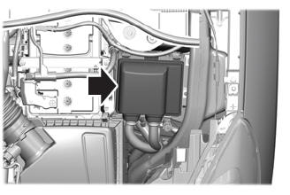
Accessing the Under Hood Fuse Box