Ford Escape: Engine / Disassembly and Assembly of Subassemblies - Cylinder Head
Special Tool(s) / General Equipment
 |
303-300
(T87C-6565-A)
Set, Valve Spring Compressor TKIT-1988-FESTIVA T88C-1000-ST TKIT-1988-TRACER TKIT-2009TC-F |
.jpg) |
303-350
(T89P-6565-A)
Compressor, Valve Spring TKIT-1990-LMH TKIT-1989-F TKIT-1989-FM TKIT-1989-FLM |
.jpg) |
303-468
(T94P-6510-AH)
Remover, Valve Stem Oil Seal TKIT-1994-LMH/MH2 TKIT-1994-FH/FMH/FLMH |
 |
303-470
(T94P-6510-CH)
Installer, Valve Stem Oil Seal TKIT-1994-LMH/MH2 TKIT-2009TC-F TKIT-1994-FH/FMH/FLMH |
 |
303-472
(T94P-6565-AH)
Adapter, Valve Spring Compressor TKIT-1994-LMH/MH2 TKIT-1994-FH/FMH/FLMH |
 |
307-005
(T59L-100-B)
Slide Hammer |
Materials
| Name | Specification |
|---|---|
| Motorcraft® Multi-Purpose Grease Spray XL-5-A |
ESB-M1C93-B |
DISASSEMBLY
NOTE: During engine repair procedures, cleanliness is extremely important. Any foreign material, including material created while cleaning gasket surfaces, that enters the oil passages, coolant passages or the oil pan can cause engine failure.
NOTE: Aluminum surfaces are soft and can be scratched easily. Never place the cylinder head gasket surface, unprotected, on a bench surface.
NOTE: If the components are to be reinstalled, they must be installed in the same positions. Mark the components removed for locations.
-
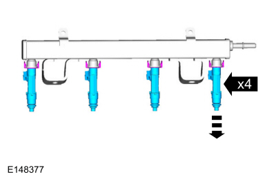
Remove the bolts and the fuel rail.
 |
-
Remove the bolts and the fuel rail.
 |
-
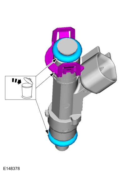
Remove and discard the fuel injector O-ring seals and the fuel injector clips.
 |
-
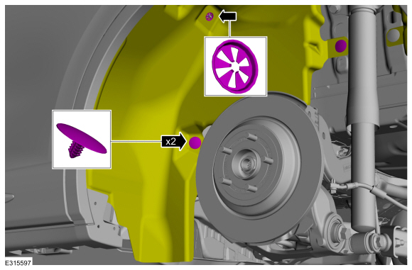
Remove the bolt and the lifting bracket.
.jpg) |
-
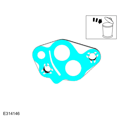
Remove the blanking plate.
.jpg) |
-
Remove and discard the blanking plate gasket.
 |
-
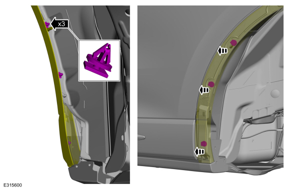
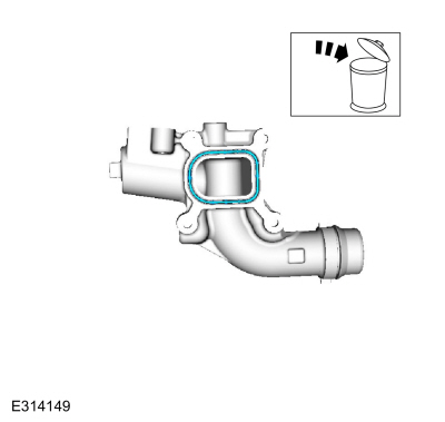
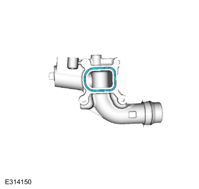
Remove the bolts and the water outlet housing.
.jpg) |
-
Remove and discard the water outlet housing gasket.
 |
-
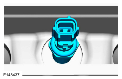
Remove and discard the CHT sensor.
 |
-
NOTE: Only use hand tools when removing or installing the spark plugs or damage can occur to the cylinder head or spark plug.
Remove the spark plugs.
.jpg) |
-
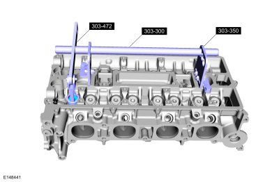
NOTE: Use a small screwdriver and multi-purpose grease to remove the valve collets.
Using the special tools, remove the valve collets, valve spring retainers and the valve springs.
Use Special Service Tool: 303-300 (T87C-6565-A) Set, Valve Spring Compressor. , 303-350 (T89P-6565-A) Compressor, Valve Spring. , 303-472 (T94P-6565-AH) Adapter, Valve Spring Compressor.
Material: Motorcraft® Multi-Purpose Grease Spray / XL-5-A (ESB-M1C93-B)
.jpg) |
-
Inspect and install new parts, as necessary.
 |
-
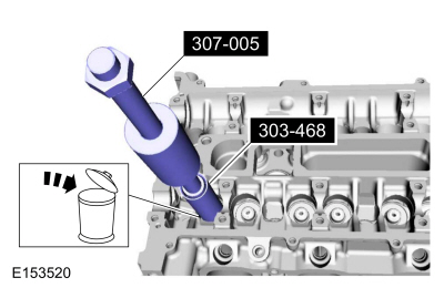
Using the special tools, remove and discard the valve seals.
Use Special Service Tool: 303-468 (T94P-6510-AH) Remover, Valve Stem Oil Seal. , 307-005 (T59L-100-B) Slide Hammer.
 |
-
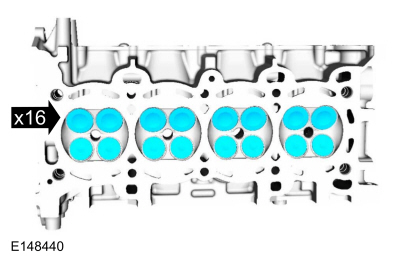
NOTE: Note the location of the valves if they are to be reused.
Remove the valves.
 |
-
NOTE: Install new parts as necessary.
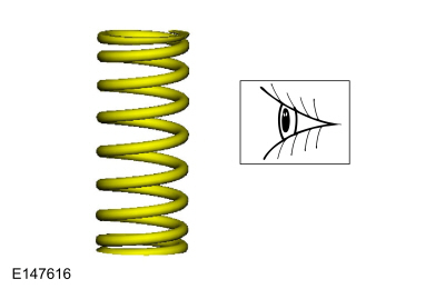
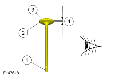
Inspect the following valve areas:
-
The end of the stem or grooves or scoring.
-
The valve face and the edge for pits, grooves or scores.
-
The valve head for signs of burning, erosion, warpage and cracking.
-
The valve margin for wear.
-
The end of the stem or grooves or scoring.
 |
ASSEMBLY
-
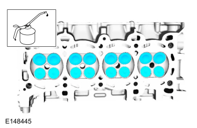
NOTE: If installing the original valves, make sure the valves are installed in the same position from which they were removed. Coat the valve stems with clean engine oil.
NOTE: Component(s) must be lubricated with clean engine oil.
Refer to: Specifications (303-01C Engine, Specifications).
 |
-
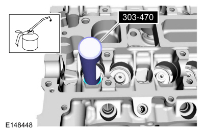
NOTE: Use the protector provided with the replacement kit to prevent damage to the valve seals.
Lubricate with clean engine oil and using the special tool, install the valve seal.
Refer to: Specifications (303-01C Engine, Specifications).
Use Special Service Tool: 303-470 (T94P-6510-CH) Installer, Valve Stem Oil Seal.
 |
-
NOTE: Use a small screwdriver and multi-purpose grease to install the valve collets.
NOTE: Check the seating of the valve collets after installation.
Using the special tools, install the valve springs, valve spring retainers and the valve collets.
Use Special Service Tool: 303-300 (T87C-6565-A) Set, Valve Spring Compressor. , 303-350 (T89P-6565-A) Compressor, Valve Spring. , 303-472 (T94P-6565-AH) Adapter, Valve Spring Compressor.
Material: Motorcraft® Multi-Purpose Grease Spray / XL-5-A (ESB-M1C93-B)
 |
-
NOTE: Only use hand tools when removing or installing the spark plugs or damage can occur to the cylinder head or spark plug.
Install the spark plugs.
Torque: 106 lb.in (12 Nm)
|
-
Install a new CHT sensor.
Torque: 106 lb.in (12 Nm)
 |
-
Install a new water outlet housing gasket.
 |
-
Install the water outlet housing and install the bolts hand tight.
-
Tighten in the sequence shown.
Torque:
Stage 1: 89 lb.in (10 Nm)
Stage 2: 45°
-
Tighten in the sequence shown.
|
-
Install a new blanking plate gasket.
.jpg) |
-
Install the blanking plate and bolts.
Torque: 177 lb.in (20 Nm)
|
-
Install the lifting bracket and the bolt.
Torque: 39 lb.ft (53 Nm)
|
-
NOTICE: Use O-ring seals that are made of special fuel-resistant material. Use of ordinary O-rings can cause the fuel system to leak. Do not reuse the O-ring seals.
NOTE: Make sure that new fuel injector O-ring seals and new fuel injector retainer clips are installed.
Install the new fuel injector O-ring seals and the fuel injector clips. Lubricate the new O-rings with clean engine oil.
Refer to: Specifications (303-01C Engine, Specifications).
.jpg) |
-
Install the fuel injectors into the fuel rail.
.jpg) |
-
Install the fuel rail assembly and the studs.
Torque:
Stage 1: 18 lb.ft (25 Nm)
Stage 2: 30°
|

 Disassembly and Assembly of Subassemblies - Piston
Materials
Name
Specification
Engine Oil - SAE 5W-20 - Synthetic Blend Motor OilXO-5W20-Q1SP
WSS-M2C945-B1
DISASSEMBLY
Remove and discard the piston rings...
Other information:
Ford Escape 2020-2026 Service Manual: Removal and Installation - Fuel Level Sender
Removal NOTE: Removal steps in this procedure may contain installation details. Remove the fuel pump sender unit. Disconnect the electrical connector. NOTE: Take extra care not to damage the fuel tank level sensor float and arm...
Ford Escape 2020-2026 Service Manual: Description and Operation - Horn - System Operation and Component Description
System Operation System Diagram E341593 *.sttxt { visibility: hidden; } *.stcallout { visibility: visible; } 1 Horns 2 Horn Switch 3 BCM-C 4 BCM 5 SCCM 6 Clockspring Item Description 1 Horns 2 Horn Switch 3 BCM-C 4 BCM 5 SCCM 6 Clockspring Horn Opera..
Categories
- Manuals Home
- 4th Generation Ford Escape Owners Manual
- 4th Generation Ford Escape Service Manual
- General Procedures - Brake Service Mode Activation and Deactivation
- Electric Parking Brake
- Drive Modes
- New on site
- Most important about car
Under Hood Fuse Box
Locating the Under Hood Fuse Box

Accessing the Under Hood Fuse Box
