Ford Escape 2020-2026 Service Manual / Chassis / Suspension / Suspension System - General Information / General Procedures - Front Toe Adjustment
Ford Escape: Suspension System - General Information / General Procedures - Front Toe Adjustment
Special Tool(s) / General Equipment
| Wheel Alignment System |
Adjustment
NOTE: Make sure that the vehicle is standing on a level surface.
NOTE: Before carrying out a toe adjustment, check the tires for the correct pressure. Inspect the tires for incorrect wear or damage. Inspect the suspension for wear or damage.
-
Using alignment equipment and the manufacturer's instructions, measure the front toe.
-
Steering wheel in straight ahead position.
 |
-
Using alignment equipment and the manufacturer's instructions, check the front toe setting on both sides.
Use the General Equipment: Wheel Alignment System
-
NOTICE: Hold the tie-rod end stationary with a wrench while loosening the nut or damage to the boot can occur.
On both sides.
-
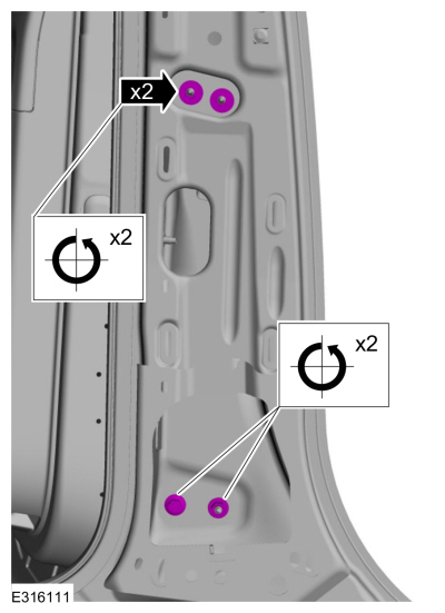
Position aside the steering gear boot clamp.
-
Loosen the outer tie rod end jamb nut.
-
NOTE: Do not allow the steering gear bellows to twist when the inner tie rod is rotated.
Rotate the inner tie-rods an equal amount in either a clockwise or a counterclockwise direction to adjust the toe setting on both sides.
-
Position aside the steering gear boot clamp.
 |
-
NOTE: Do not disturb the toe settings while tightening the nut(s).
On both sides.
-
Tighten the outer tie rod end jamb nut.
Torque: 66 lb.ft (90 Nm)
-
Position the steering gear boot clamp.
-
Tighten the outer tie rod end jamb nut.
 |
-
Recheck the toe settings and adjust as necessary.
 Diagnosis and Testing - Suspension System
Symptom Chart: Suspension System
Diagnostics in this manual assume a certain skill level and knowledge of Ford-specific diagnostic practices.REFER to: Diagnostic Methods (100-00 General Information, Description and Operation)...
 General Procedures - Rear Toe Adjustment
Special Tool(s) /
General Equipment
Wheel Alignment System
Adjustment
NOTICE:
Do not use any tools or equipment to move the wheel and tire
assembly or suspension components while checking for relative movement...
Other information:
Ford Escape 2020-2026 Service Manual: Removal and Installation - Generator Pulley
Removal WARNING: Before beginning any service procedure in this section, refer to Safety Warnings in section 100-00 General Information. Failure to follow this instruction may result in serious personal injury. Follow the health and safety precautions...
Ford Escape 2020-2026 Service Manual: Diagnosis and Testing - Wireless Accessory Charging Module (WACM)
Diagnostic Trouble Code (DTC) Chart Diagnostics in this manual assume a certain skill level and knowledge of Ford-specific diagnostic practices. REFER to: Diagnostic Methods (100-00 General Information, Description and Operation). Module DTC Description Action BCM B1554:11 Wireless Accessory Charger Enable/Disable: Circuit Short To Ground GO to Pinpoint Test A BCM B1554:13..
Categories
- Manuals Home
- 4th Generation Ford Escape Owners Manual
- 4th Generation Ford Escape Service Manual
- All-Wheel Drive
- Removal and Installation - All-Wheel Drive (AWD) Module - 1.5L EcoBoost (132kW/180PS) – I3 (Y1)/2.0L EcoBoost (177kW/240PS) – MI4
- What Is the Tire Pressure Monitoring System. Tire Pressure Monitoring System Overview
- New on site
- Most important about car
Push Button Ignition Switch

Switching the Ignition Off
When the ignition is on or in accessory mode, press the push button ignition switch once without your foot on the brake pedal.
Copyright © 2026 www.fordescape4.com