Ford Escape: Side Panel Sheet Metal Repairs / Removal and Installation - A-Pillar Outer Panel Section and Reinforcement
Special Tool(s) / General Equipment
| Resistance Spotwelding Equipment | |
| Spherical Cutter | |
| Hot Air Gun | |
| 8 mm Drill Bit | |
| MIG/MAG Welding Equipment | |
| Spot Weld Drill Bit | |
| Locking Pliers |
Materials
| Name | Specification |
|---|---|
| Metal Bonding Adhesive TA-1, TA-1-B, 3M™ 08115, LORD Fusor® 108B, Henkel Teroson EP 5055 |
- |
| Flexible Foam Repair 3M™ 08463, LORD Fusor® 121 |
- |
Removal
 WARNING:
Electric vehicles damaged by a crash may have compromised
high voltage safety systems and present a potential high voltage
electrical shock hazard. Exercise caution and wear appropriate Personal
Protective Equipment (PPE) safety gear, including high voltage safety
gloves and boots. Remove all metallic jewelry, including watches and
rings. Isolate the HV system as directed by the Ford Emergency Response
Guide for the vehicle. Failure to follow these instructions may result
in serious personal injury or death.
WARNING:
Electric vehicles damaged by a crash may have compromised
high voltage safety systems and present a potential high voltage
electrical shock hazard. Exercise caution and wear appropriate Personal
Protective Equipment (PPE) safety gear, including high voltage safety
gloves and boots. Remove all metallic jewelry, including watches and
rings. Isolate the HV system as directed by the Ford Emergency Response
Guide for the vehicle. Failure to follow these instructions may result
in serious personal injury or death.
NOTICE: BEV , HEV and PHEV contain a high-voltage battery. Before cutting or welding near the high-voltage battery it must be removed to avoid damage.
NOTE: Left hand (LH) side shown, right hand (RH) side similar.
NOTE: The A-pillar reinforcement is constructed of boron steel and cannot be sectioned. It must be replaced at factory seams.
-
Refer to: Health and Safety Precautions (100-00 General Information, Description and Operation).
WARNING:
Before beginning any service procedure in this
manual, refer to health and safety warnings in section 100-00 General
Information. Failure to follow this instruction may result in serious
personal injury.
Refer to: High Voltage System Health and Safety Precautions - Overview (100-00 General Information, Description and Operation).
-
Depower the SRS .
Refer to: Supplemental Restraint System (SRS) Depowering (501-20B Supplemental Restraint System, General Procedures).
-
Remove the fender and splash shield.
Refer to: Fender (501-02 Front End Body Panels, Removal and Installation).
Refer to: Fender Splash Shield (501-02 Front End Body Panels, Removal and Installation).
-
Remove the welds and fender bracket.
Use the General Equipment: Spot Weld Drill Bit
.jpg) |
-
Remove the bolt.
 |
-
Remove the welds and gusset.
Use the General Equipment: Spot Weld Drill Bit
Use the General Equipment: Spherical Cutter
.jpg) |
-
Remove the A-pillar outer panel.
Refer to: A-Pillar Outer Panel (501-29 Side Panel Sheet Metal Repairs, Removal and Installation).
-
Remove the A-pillar lower reinforcement bolt.
.jpg) |
-
Remove the welds and the upper A-pillar reinforcement.
Use the General Equipment: Spot Weld Drill Bit
.jpg) |
-
Remove the welds.
Use the General Equipment: Spot Weld Drill Bit
.jpg) |
-
Remove the welds and the lower A-pillar reinforcement.
Use the General Equipment: Spot Weld Drill Bit
Use the General Equipment: Hot Air Gun
.jpg) |
Installation
WARNING:
Electric vehicles damaged by a crash may have compromised
high voltage safety systems and present a potential high voltage
electrical shock hazard. Exercise caution and wear appropriate Personal
Protective Equipment (PPE) safety gear, including high voltage safety
gloves and boots. Remove all metallic jewelry, including watches and
rings. Isolate the HV system as directed by the Ford Emergency Response
Guide for the vehicle. Failure to follow these instructions may result
in serious personal injury or death.
NOTICE: BEV , HEV and PHEV contain a high-voltage battery. Before cutting or welding near the high-voltage battery it must be removed to avoid damage.
NOTICE: The high-voltage battery in a battery electric vehicle (BEV), hybrid electric vehicle (HEV) or plug-in hybrid electric vehicle (PHEV) can be affected and damaged by excessively high temperatures. The temperature in some body shop paint booths can exceed 60° C (140° F). Therefore, during refinishing operations, the paint booth temperature must set at or below 60° C (140° F) with a bake time of 45 minutes or less. Temperatures in excess of 60° C (140° F) or bake durations longer than 45 minutes will require the high-voltage battery be removed from the vehicle prior to placing in the paint booth.
NOTICE: If refinishing cure temperatures exceed 60° C (140° F), the charge port light ring on plug-in vehicles must be removed.
NOTE: Factory welds may be substituted with resistance or metal active gas (MAG) plug welds. Resistance welds may not be placed directly over original location. They must be placed adjacent to original location and match factory welds in quantity. Metal active gas (MAG) plug welds must equal factory welds in both location and quantity.
NOTE: Left hand (LH) side shown, right hand (RH) side similar.
-
Refer to: Health and Safety Precautions (100-00 General Information, Description and Operation).
WARNING:
Before beginning any service procedure in this
manual, refer to health and safety warnings in section 100-00 General
Information. Failure to follow this instruction may result in serious
personal injury.
Refer to: High Voltage System Health and Safety Precautions - Overview (100-00 General Information, Description and Operation).
-
Drill plug weld holes.
Use the General Equipment: 8 mm Drill Bit
.jpg) |
-
Drill plug weld holes.
Use the General Equipment: 8 mm Drill Bit
.jpg) |
-
Apply adhesive.
Material: Metal Bonding Adhesive / TA-1, TA-1-B, 3M™ 08115, LORD Fusor® 108B, Henkel Teroson EP 5055
.jpg) |
-
Install, properly position, clamp and weld the lower A-pillar reinforcement.
Use the General Equipment: Locking Pliers
Use the General Equipment: Resistance Spotwelding Equipment
.jpg) |
-
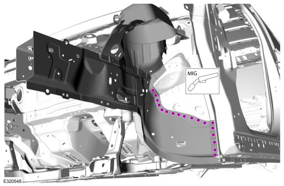
Install the welds.
Use the General Equipment: MIG/MAG Welding Equipment
.jpg) |
-
Install, properly position, clamp and weld the A-pillar upper reinforcement/
Use the General Equipment: Locking Pliers
Use the General Equipment: Resistance Spotwelding Equipment
Use the General Equipment: MIG/MAG Welding Equipment
.jpg) |
-
Metal finish all welds as necessary using typical metal finish techniques.
-
Install the bolt.
Torque: 35 lb.ft (47 Nm)
|
-
Install NVH foam sealant in areas noted during removal.
Material: Flexible Foam Repair / 3M™ 08463, LORD Fusor® 121
.jpg) |
-
Drill plug weld holes.
Use the General Equipment: 8 mm Drill Bit
.jpg) |
-
Install, properly position and clamp the fender apron bracket.
Use the General Equipment: Locking Pliers
.jpg) |
-
Install the welds.
Use the General Equipment: Resistance Spotwelding Equipment
.jpg) |
-
Install the welds.
Use the General Equipment: MIG/MAG Welding Equipment
.jpg) |
-
Install the bolt.
Torque: 35 lb.ft (47 Nm)
|
-
Install the A-pillar outer panel.
Refer to: A-Pillar Outer Panel (501-29 Side Panel Sheet Metal Repairs, Removal and Installation).
-
Restore corrosion protection.
Refer to: Corrosion Prevention (501-25 Body Repairs - General Information, General Procedures).
-
Repower the SRS .
Refer to: Supplemental Restraint System (SRS) Repowering (501-20B Supplemental Restraint System, General Procedures).

 Removal and Installation - B-Pillar and Reinforcement
Special Tool(s) /
General Equipment
Resistance Spotwelding Equipment
Scraper for Straight Edges
Hot Air Gun
8 mm Drill Bit
MIG/MAG Welding Equipment
Spot Weld Drill Bit
Locking Pliers
Materials
Name
Specification
Metal Bonding AdhesiveTA-1, TA-1-B, 3M™ 08115, LORD Fusor® 108B, Henkel Teroson EP 5055
-
Seam SealerTA-2-B, 3M™ 08308, ..
Other information:
Ford Escape 2020-2024 Service Manual: Removal and Installation - Wheel Knuckle
Special Tool(s) / General Equipment 204-161 (T97P-1175-A) Installer, HalfshaftTKIT-1997-LM2TKIT-1997-F/FM2TKIT-1997-FLM2 205-D070 (D93P-1175-B) Remover, Front Wheel Hub Tie Rod End Remover Removal NOTICE: Suspension fasteners are critical parts that affect the performance of vital components and systems. Failure of these fasteners may result in major service expe..
Ford Escape 2020-2024 Service Manual: Diagnosis and Testing - Wheels and Tires
Preliminary Inspection Verify the customer concern by carrying out a road test on a smooth road. If any vibrations are apparent, Refer to the Symptom Chart: NVH. To maximize tire performance, inspect for signs of incorrect inflation and uneven wear, which may indicate a need for balancing, rotation or front suspension alignment. Correct tire pressure and driving techniques..
Categories
- Manuals Home
- 4th Generation Ford Escape Owners Manual
- 4th Generation Ford Escape Service Manual
- Accessing the Trip Computer. Resetting the Trip Computer
- Plug-In Hybrid Electric Vehicle Drive Modes
- Child Safety Locks
- New on site
- Most important about car
Vehicle Identification
Locating the Vehicle Identification Number
The vehicle identification number is on the left-hand side of the instrument panel.
