Ford Escape: Front Suspension / Removal and Installation - Wheel Knuckle
Special Tool(s) / General Equipment
 |
204-161
(T97P-1175-A)
Installer, Halfshaft TKIT-1997-LM2 TKIT-1997-F/FM2 TKIT-1997-FLM2 |
 |
205-D070
(D93P-1175-B)
Remover, Front Wheel Hub |
| Tie Rod End Remover | |
Removal
NOTICE: Suspension fasteners are critical parts that affect the performance of vital components and systems. Failure of these fasteners may result in major service expense. Use the same or equivalent parts if replacement is necessary. Do not use a replacement part of lesser quality or substitute design. Tighten fasteners as specified.
NOTE: Removal steps in this procedure may contain installation details.
-
Remove the wheel and tire.
Refer to: Wheel and Tire (204-04A Wheels and Tires, Removal and Installation).
-
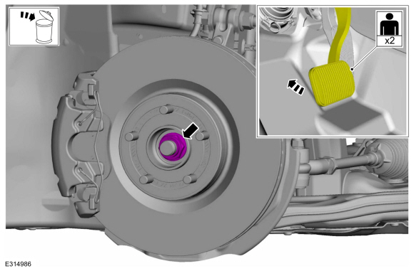
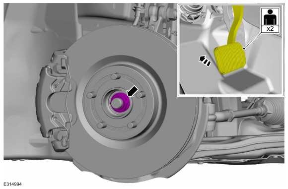
NOTE: Apply the brake to prevent the halfshaft from rotating while loosening the wheel hub nut.
Remove and discard the wheel hub nut.
 |
-
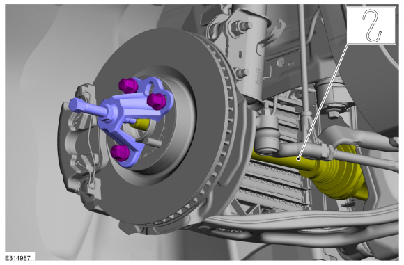
NOTICE: Do not bend the inner joint more than 18 degrees and the outer joint more than 45 degrees. Damage to the halfshaft will occur.
Using the special tool, press the halfshaft from the wheel bearing and hub. Support the halfshaft in a level position.
Use Special Service Tool: 205-D070 (D93P-1175-B) Remover, Front Wheel Hub.
 |
-
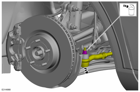
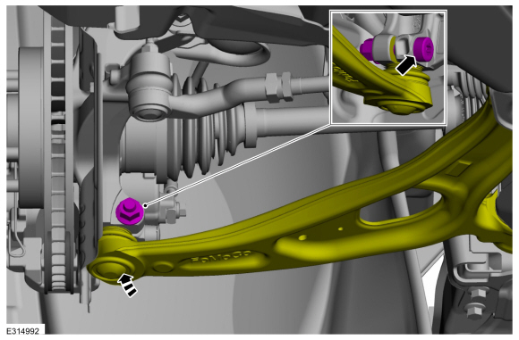
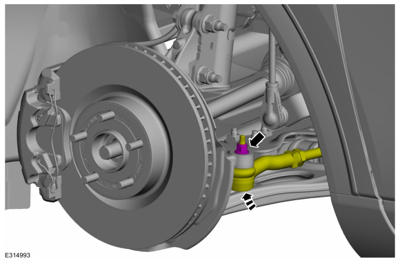
NOTICE: Do not use a hammer to separate the tie rod end from the wheel knuckle or damage to the wheel knuckle may result.
NOTICE: Use care when installing the tie rod separator or damage to the tie rod end boot may occur.
NOTE: Use the hex-holding feature to prevent turning of the stud while removing the tie rod end nut.
Remove and discard the tie rod end nut and separate the tie rod end from the wheel knuckle.
Use the General Equipment: Tie Rod End Remover
 |
-
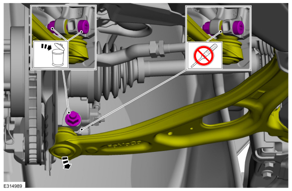
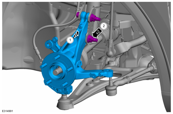
NOTICE: Do not use a prying device to open the slot in the knuckle to separate the lower ball joint from the knuckle assembly. Damage to the knuckle assembly may occur.
NOTICE: Do not use a prying device or separator fork between the ball joint and the wheel knuckle. Damage to the ball joint or ball joint seal may result. Only use the pry bar by inserting it into the lower arm body opening.
NOTICE: Use care when releasing the lower arm and wheel knuckle into the resting position or damage to the ball joint seal may occur.
NOTICE: Do not use power tools to remove or install the lower arm outboard nut. Damage to the ball joint or ball joint seal may occur.
NOTE: Use the TORX PLUS® holding feature to prevent the ball stud from turning while removing or installing the lower arm outboard nut. Torx® and TORX PLUS® is a reg. tm of Acument Intellectual Properties, LLC.
Remove and discard the ball joint pinch bolt and nut and separate the lower arm from the wheel knuckle.
 |
-
Remove the front wheel speed sensor.
Refer to: Front Wheel Speed Sensor (206-09 Anti-Lock Brake System (ABS) and Stability Control, Removal and Installation).
-
Remove the brake disc shield.
Refer to: Brake Disc Shield (206-03 Front Disc Brake, Removal and Installation).
-
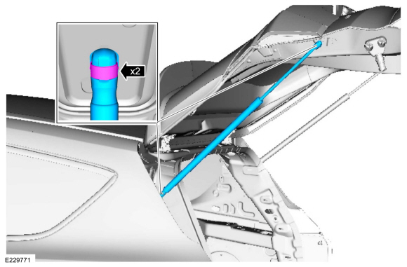
Remove and discard the lower strut-to-wheel knuckle bolts and nuts and remove the wheel knuckle.
 |
Installation
NOTICE: Tighten the suspension fasteners with the weight of the vehicle on the wheels and tires or use a suitable jack to raise the suspension to curb height or damage to the bushings may occur.
-
-
Position the wheel knuckle to the lower strut assembly.
-
Install the new lower strut-to-wheel knuckle bolts and nuts.
Torque:
Stage 1: 103 lb.ft (140 Nm)
Stage 2: 120°
-
Position the wheel knuckle to the lower strut assembly.
 |
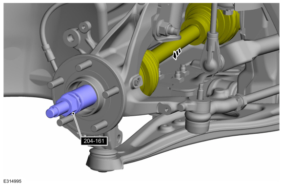
-
Using special tools, pull the halfshaft into the hub.
Use Special Service Tool: 204-161 (T97P-1175-A) Installer, Halfshaft.
 |
-
Install the brake disc shield.
Refer to: Brake Disc Shield (206-03 Front Disc Brake, Removal and Installation).
-
Install the front wheel speed sensor.
Refer to: Front Wheel Speed Sensor (206-09 Anti-Lock Brake System (ABS) and Stability Control, Removal and Installation).
-
NOTICE: Do not use power tools to remove or install the lower arm outboard nut. Damage to the ball joint or ball joint seal may occur.
NOTE: Use the TORX PLUS® holding feature to prevent the ball stud from turning while removing or installing the lower arm outboard nut. Torx® and TORX PLUS® is a reg. tm of Acument Intellectual Properties, LLC.
Attach the lower arm to the wheel knuckle and install the new ball joint pinch bolt and nut.
Torque: 66 lb.ft (90 Nm)
 |
-
NOTICE: Use care when installing the tie rod separator or damage to the tie rod end boot may occur.
NOTE: Use the hex-holding feature to prevent turning of the stud while installing the tie rod end nut.
Attach the tie rod end to the wheel knuckle and install the new tie rod end nut.
Torque: 35 lb.ft (48 Nm)
 |
-
NOTICE: Do not tighten the front wheel hub nut with the vehicle on the ground. The nut must be tightened to specification before the vehicle is lowered onto the wheels. Wheel bearing damage will occur if the wheel bearing is loaded with the weight of the vehicle applied.
NOTICE: Install and tighten the new wheel hub nut to specification in a continuous rotation. Always install a new wheel hub nut after loosening or when not tightened to specification in a continuous rotation or damage to the components may occur.
NOTE: Apply the brake to keep the halfshaft from rotating.
While an assistant applies the brake, install the new wheel hub nut.
Torque:
Stage 1: 74 lb.ft (100 Nm)
Stage 2: 60°
 |
-
Install the wheel and tire.
Refer to: Wheel and Tire (204-04A Wheels and Tires, Removal and Installation).
-
Check and if necessary adjust the front toe.
Refer to: Front Toe Adjustment (204-00 Suspension System - General Information, General Procedures).
 Removal and Installation - Lower Arm Bushing
Special Tool(s) /
General Equipment
204-830Remover/Installer, Bushing Lower Arm
204-833Remover/Installer, Bushing Lower Arm
204-834Remover/Installer, Front Lower Arm Bushing
Hydraulic Press
Wooden Block
Removal
NOTE:
Removal steps in this procedure may contain installation details...
 Removal and Installation - Wheel Studs
Removal
NOTE:
Wheel studs are not serviceable separately. Wheel bearing and wheel hub assembly must be replaced.
Remove the front wheel bearing and wheel hub...
Other information:
Ford Escape 2020-2026 Service Manual: Diagnosis and Testing - Fog Lamps
Diagnostic Trouble Code (DTC) Chart Diagnostics in this manual assume a certain skill level and knowledge of Ford-specific diagnostic practices. REFER to: Diagnostic Methods (100-00 General Information, Description and Operation). Diagnostic Trouble Code Chart Module DTC Description Action BCM B1147..
Ford Escape 2020-2026 Service Manual: Removal and Installation - Active Grille Shutter Actuator
Special Tool(s) / General Equipment Flat Headed Screw Driver Removal NOTE: Removal steps in this procedure may contain installation details. Remove the active grille shutter. Refer to: Active Grille Shutter (501-02 Front End Body Panels, Removal and Installation). On both sides. Release the tabs and remove the upper vane bearing. Install the General Eq..
Categories
- Manuals Home
- 4th Generation Ford Escape Owners Manual
- 4th Generation Ford Escape Service Manual
- Electric Parking Brake
- Switching the Rear Window Wiper On and Off. Reverse Wipe
- Removal and Installation - All-Wheel Drive (AWD) Module - 1.5L EcoBoost (132kW/180PS) – I3 (Y1)/2.0L EcoBoost (177kW/240PS) – MI4
- New on site
- Most important about car
Vehicle Identification
Locating the Vehicle Identification Number
The vehicle identification number is on the left-hand side of the instrument panel.
