Ford Escape: Rear End Sheet Metal Repairs / Removal and Installation - Back Panel and Reinforcement
Special Tool(s) / General Equipment
| Resistance Spotwelding Equipment | |
| Scraper for Straight Edges | |
| Hot Air Gun | |
| 8 mm Drill Bit | |
| MIG/MAG Welding Equipment | |
| Spot Weld Drill Bit | |
| Locking Pliers |
Materials
| Name | Specification |
|---|---|
| Metal Bonding Adhesive TA-1, TA-1-B, 3M™ 08115, LORD Fusor® 108B, Henkel Teroson EP 5055 |
- |
| Seam Sealer TA-2-B, 3M™ 08308, LORD Fusor® 803DTM |
- |
| Flexible Foam Repair 3M™ 08463, LORD Fusor® 121 |
- |
Removal
.jpg) WARNING:
Electric vehicles damaged by a crash may have compromised
high voltage safety systems and present a potential high voltage
electrical shock hazard. Exercise caution and wear appropriate Personal
Protective Equipment (PPE) safety gear, including high voltage safety
gloves and boots. Remove all metallic jewelry, including watches and
rings. Isolate the HV system as directed by the Ford Emergency Response
Guide for the vehicle. Failure to follow these instructions may result
in serious personal injury or death.
WARNING:
Electric vehicles damaged by a crash may have compromised
high voltage safety systems and present a potential high voltage
electrical shock hazard. Exercise caution and wear appropriate Personal
Protective Equipment (PPE) safety gear, including high voltage safety
gloves and boots. Remove all metallic jewelry, including watches and
rings. Isolate the HV system as directed by the Ford Emergency Response
Guide for the vehicle. Failure to follow these instructions may result
in serious personal injury or death.
NOTICE: Battery electric vehicle (BEV), hybrid electric vehicle (HEV) and plug-in hybrid electric vehicle (PHEV) contain a high-voltage battery. Before cutting or welding near the high-voltage battery it must be removed to avoid damage.
NOTE: Left hand (LH) side shown, right hand (RH) side similar.
-
Refer to: Health and Safety Precautions (100-00 General Information, Description and Operation).
WARNING:
Before beginning any service procedure in this
manual, refer to health and safety warnings in section 100-00 General
Information. Failure to follow this instruction may result in serious
personal injury.
Refer to: High Voltage System Health and Safety Precautions - Overview (100-00 General Information, Description and Operation).
-
Remove the load space trim.
Refer to: Loadspace Scuff Plate Trim Panel (501-05 Interior Trim and Ornamentation, Removal and Installation).
-
Remove the liftgate striker.
.jpg) |
-
On both sides.
Remove the rear lamp assembly.
Refer to: Rear Lamp Assembly (417-01 Exterior Lighting, Removal and Installation).
-
Remove the rear bumper.
Refer to: Rear Bumper (501-19 Bumpers, Removal and Installation).
-
Remove the seam sealer.
Use the General Equipment: Hot Air Gun
Use the General Equipment: Scraper for Straight Edges
.jpg) |
-
Remove the spot welds.
Use the General Equipment: Spot Weld Drill Bit
.jpg) |
-
NOTE: Pay particular attention to adhesives and sealers to aid in installation.
Remove the tail panel.
Use the General Equipment: Hot Air Gun
.jpg) |
-
Remove the seam sealer.
Use the General Equipment: Hot Air Gun
Use the General Equipment: Scraper for Straight Edges
.jpg) |
-
Remove the welds.
Use the General Equipment: Spot Weld Drill Bit
.jpg) |
-
On both sides.
Remove the welds.
Use the General Equipment: Spot Weld Drill Bit
 |
-
On both sides.
Remove the welds.
Use the General Equipment: Spot Weld Drill Bit
.jpg) |
-
Remove the reinforcement.
Use the General Equipment: Hot Air Gun
.jpg) |
Installation
WARNING:
Electric vehicles damaged by a crash may have compromised
high voltage safety systems and present a potential high voltage
electrical shock hazard. Exercise caution and wear appropriate Personal
Protective Equipment (PPE) safety gear, including high voltage safety
gloves and boots. Remove all metallic jewelry, including watches and
rings. Isolate the HV system as directed by the Ford Emergency Response
Guide for the vehicle. Failure to follow these instructions may result
in serious personal injury or death.
NOTICE: Battery electric vehicle (BEV), hybrid electric vehicle (HEV) and plug-in hybrid electric vehicle (PHEV) contain a high-voltage battery. Before cutting or welding near the high-voltage battery it must be removed to avoid damage.
NOTICE: The high-voltage battery in a battery electric vehicle (BEV), hybrid electric vehicle (HEV) or plug-in hybrid electric vehicle (PHEV) can be affected and damaged by excessively high temperatures. The temperature in some body shop paint booths can exceed 60° C (140° F). Therefore, during refinishing operations, the paint booth temperature must set at or below 60° C (140° F) with a bake time of 45 minutes or less. Temperatures in excess of 60° C (140° F) or bake durations longer than 45 minutes will require the high-voltage battery be removed from the vehicle prior to placing in the paint booth.
NOTICE: If refinishing cure temperatures exceed 60° C (140° F), the charge port light ring on plug-in vehicles must be removed.
NOTE: Factory welds may be substituted with resistance or metal inert gas (MIG) plug welds. Resistance welds may not be placed directly over original location. They must be placed adjacent to original location and match factory welds in quantity. Metal inert gas (MIG) plug welds must equal factory welds in both location and quantity.
NOTE: Left hand (LH) side shown, right hand (RH) side similar.
-
Refer to: Health and Safety Precautions (100-00 General Information, Description and Operation).
WARNING:
Before beginning any service procedure in this
manual, refer to health and safety warnings in section 100-00 General
Information. Failure to follow this instruction may result in serious
personal injury.
Refer to: High Voltage System Health and Safety Precautions - Overview (100-00 General Information, Description and Operation).
-
Sand to remove old adhesive and clean.
.jpg) |
-
Apply adhesive.
Material: Metal Bonding Adhesive / TA-1, TA-1-B, 3M™ 08115, LORD Fusor® 108B, Henkel Teroson EP 5055
.jpg) |
-
Install properly position and clamp.
Use the General Equipment: Locking Pliers
.jpg) |
-
Install the welds.
Use the General Equipment: Resistance Spotwelding Equipment
.jpg) |
-
On both sides.
Install the welds.
Use the General Equipment: Resistance Spotwelding Equipment
.jpg) |
-
On both sides.
Install the welds.
Use the General Equipment: Resistance Spotwelding Equipment
.jpg) |
-
Seam Sealing:
All seams must be sealed to production level.
Material: Seam Sealer / TA-2-B, 3M™ 08308, LORD Fusor® 803DTM
.jpg) |
-
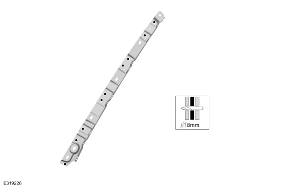
Drill plug weld holes.
Use the General Equipment: 8 mm Drill Bit
.jpg) |
-
Install properly position and clamp.
Use the General Equipment: Locking Pliers
.jpg) |
-
On both sides.
Install the welds.
Use the General Equipment: Resistance Spotwelding Equipment
Use the General Equipment: MIG/MAG Welding Equipment
.jpg) |
-
Apply NVH foam sealant in areas noted during removal.
Material: Flexible Foam Repair / 3M™ 08463, LORD Fusor® 121
.jpg) |
-
Seam Sealing:
All seams must be sealed to production level.
Material: Seam Sealer / TA-2-B, 3M™ 08308, LORD Fusor® 803DTM
.jpg) |
-
Refinish the entire repair using a Ford approved paint system.
-
Restore corrosion protection.
Refer to: Corrosion Prevention (501-25 Body Repairs - General Information, General Procedures).
-
Install the liftgate striker.
Torque: 18 lb.ft (25 Nm)
|
-
Install the load space trim.
Refer to: Loadspace Scuff Plate Trim Panel (501-05 Interior Trim and Ornamentation, Removal and Installation).
-
On both sides.
Install the rear lamp assembly.
Refer to: Rear Lamp Assembly (417-01 Exterior Lighting, Removal and Installation).
-
Install the rear bumper and cover.
Refer to: Rear Bumper (501-19 Bumpers, Removal and Installation).
Refer to: Rear Bumper Cover (501-19 Bumpers, Removal and Installation).
-
Align the liftgate.
Refer to: Liftgate Alignment (501-03 Body Closures, General Procedures).

 Removal and Installation - Inner Quarter Panel
Special Tool(s) /
General Equipment
Resistance Spotwelding Equipment
Scraper for Straight Edges
Hot Air Gun
8 mm Drill Bit
MIG/MAG Welding Equipment
Spot Weld Drill Bit
Locking Pliers
Materials
Name
Specification
Seam SealerTA-2-B, 3M™ 08308, LORD Fusor® 803DTM
-
Flexible Foam Repair3M™ 08463, LORD Fusor® 121
-
Remo..
Other information:
Ford Escape 2020-2026 Service Manual: Description and Operation - Cruise Control - System Operation and Component Description
System Operation Adaptive Cruise Control Item Description 1 IPC 2 Accelerator pedal 3 Deactivator switch 4 Stoplamp switch 5 Brake switch assembly 6 SCCM 7 PCM 8 Cruise control switches 9 IPMA 10 BCM 11 ABS module 12 GWM 13 RCM 14 CCM Netwo..
Ford Escape 2020-2026 Owners Manual: Autounlock. Autolock. Mislock. Doors and Locks Audible Warnings
Autounlock What Is Autounlock Autounlock is an unlocking feature that unlocks the vehicle doors when your vehicle comes to a stop. Autounlock Requirements Autounlock unlocks all the doors when all of the following occur: The ignition is on, all the doors are closed and your vehicle is moving at a speed greater than 12 mph (20 km/h). Your vehicle comes to a stop. You open the driver door..
Categories
- Manuals Home
- 4th Generation Ford Escape Owners Manual
- 4th Generation Ford Escape Service Manual
- Power Outlet - Vehicles With: 12V Power Outlet
- Switching the Rear Window Wiper On and Off. Reverse Wipe
- Accessing the Trip Computer. Resetting the Trip Computer
- New on site
- Most important about car
Master Access Code
What Is the Master Access Code
The master access code is a factory-set five-digit entry code. You can operate the keypad with the master access code at any time. The master access code is on the owner’s wallet card in the glove box and is available from an authorized dealer.
Displaying the Master Access Code
To display the factory-set code in the information display:
