Ford Escape: Rear End Sheet Metal Repairs / Removal and Installation - Inner Quarter Panel
Special Tool(s) /
General Equipment
| Resistance Spotwelding Equipment |
| Scraper for Straight Edges |
| Hot Air Gun |
| 8 mm Drill Bit |
| MIG/MAG Welding Equipment |
| Spot Weld Drill Bit |
| Locking Pliers |
Materials
| Name |
Specification |
Seam Sealer
TA-2-B, 3M™ 08308, LORD Fusor® 803DTM |
-
|
Flexible Foam Repair
3M™ 08463, LORD Fusor® 121 |
-
|
Removal
.jpg) WARNING:
Electric vehicles damaged by a crash may have compromised
high voltage safety systems and present a potential high voltage
electrical shock hazard. Exercise caution and wear appropriate Personal
Protective Equipment (PPE) safety gear, including high voltage safety
gloves and boots. Remove all metallic jewelry, including watches and
rings. Isolate the HV system as directed by the Ford Emergency Response
Guide for the vehicle. Failure to follow these instructions may result
in serious personal injury or death.
WARNING:
Electric vehicles damaged by a crash may have compromised
high voltage safety systems and present a potential high voltage
electrical shock hazard. Exercise caution and wear appropriate Personal
Protective Equipment (PPE) safety gear, including high voltage safety
gloves and boots. Remove all metallic jewelry, including watches and
rings. Isolate the HV system as directed by the Ford Emergency Response
Guide for the vehicle. Failure to follow these instructions may result
in serious personal injury or death.
NOTICE:
Battery electric vehicle (BEV), hybrid electric vehicle
(HEV) and plug-in hybrid electric vehicle (PHEV) contain a high-voltage
battery. Before cutting or welding near the high-voltage battery it must
be removed to avoid damage.
NOTE:
Left hand (LH) side shown, right hand (RH) side similar.
NOTE:
Sectioning may not take place within 50 mm of restraints, door hinge, door striker or suspension mounting points.
NOTE:
The inner quarter panel is constructed of mild steel and may
be sectioned providing section guidelines are met. The following
assumes full component replacement. Adjust to meet repair requirements.
-
WARNING:
Before beginning any service procedure in this
manual, refer to health and safety warnings in section 100-00 General
Information. Failure to follow this instruction may result in serious
personal injury.
Refer to: Health and Safety Precautions (100-00 General Information, Description and Operation).
Refer to: High Voltage System Health and Safety Precautions - Overview (100-00 General Information, Description and Operation).
-
Depower the SRS .
Refer to: Supplemental Restraint System (SRS) Depowering (501-20B Supplemental Restraint System, General Procedures).
-
If Necessary:
Dimensionally restore the vehicle to a pre-damage condition.
Refer to: Body and Frame (501-26 Body Repairs - Vehicle Specific Information and Tolerance Checks, Description and Operation).
-
Remove the rear seat.
Refer to: Rear Seat (501-10B Rear Seats, Removal and Installation).
-
Remove the load space trim.
Refer to: Loadspace Scuff Plate Trim Panel (501-05 Interior Trim and Ornamentation, Removal and Installation).
Refer to: Loadspace Trim Panel (501-05 Interior Trim and Ornamentation, Removal and Installation).
-
Remove the outer back panel only.
Refer to: Back Panel and Reinforcement (501-30 Rear End Sheet Metal Repairs, Removal and Installation).
-
Remove the roof or roof opening panel.
Refer to: Roof Panel (501-28 Roof Sheet Metal Repairs, Removal and Installation).
Refer to: Roof Opening Panel Frame (501-17 Roof Opening Panel, Removal and Installation).
-
Remove the rear roof header panel and rear roof bow.
Refer to: Roof Rear Frame (501-28 Roof Sheet Metal Repairs, Removal and Installation).
Refer to: Roof Reinforcement (501-28 Roof Sheet Metal Repairs, Removal and Installation).
-
Remove the quarter panel.
Refer to: Quarter Panel (501-30 Rear End Sheet Metal Repairs, Removal and Installation).
-
Remove the water drain panel.
Refer to: Water Drain Panel (501-30 Rear End Sheet Metal Repairs, Removal and Installation).
-
Remove the rocker panel.
Refer to: Rocker Panel (501-29 Side Panel Sheet Metal Repairs, Removal and Installation).
-
Remove the push pins and fuel filler bowl.
-
Position the carpeting and all wiring harnesses away from the working area.
-
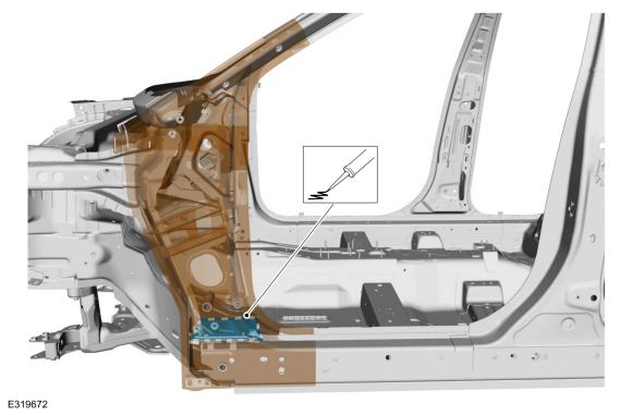
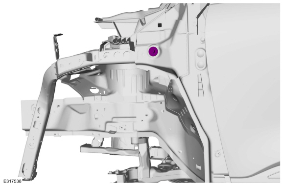
Remove the bolts.
-
Remove the welds.
Use the General Equipment: Spot Weld Drill Bit
-
Remove the reinforcement.
-
Remove the welds.
Use the General Equipment: Spot Weld Drill Bit
-
Remove the welds.
Use the General Equipment: Spot Weld Drill Bit
-
Remove the welds.
Use the General Equipment: Spot Weld Drill Bit
-
NOTE:
Pay particular attention to location of adhesives, sealers and NVH materials to aid in installation.
Remove the seam sealer and NVH material.
Use the General Equipment: Hot Air Gun
Use the General Equipment: Scraper for Straight Edges
-
Remove the welds.
Use the General Equipment: Spot Weld Drill Bit
-
Remove the welds.
Use the General Equipment: Spot Weld Drill Bit
-
Remove the inner quarter panel.
Installation
WARNING:
Electric vehicles damaged by a crash may have compromised
high voltage safety systems and present a potential high voltage
electrical shock hazard. Exercise caution and wear appropriate Personal
Protective Equipment (PPE) safety gear, including high voltage safety
gloves and boots. Remove all metallic jewelry, including watches and
rings. Isolate the HV system as directed by the Ford Emergency Response
Guide for the vehicle. Failure to follow these instructions may result
in serious personal injury or death.
NOTICE:
Battery electric vehicle (BEV), hybrid electric vehicle
(HEV) and plug-in hybrid electric vehicle (PHEV) contain a high-voltage
battery. Before cutting or welding near the high-voltage battery it must
be removed to avoid damage.
NOTICE:
The high-voltage battery in a battery electric vehicle
(BEV), hybrid electric vehicle (HEV) or plug-in hybrid electric vehicle
(PHEV) can be affected and damaged by excessively high temperatures. The
temperature in some body shop paint booths can exceed 60° C (140° F).
Therefore, during refinishing operations, the paint booth temperature
must set at or below 60° C (140° F) with a bake time of 45 minutes or
less. Temperatures in excess of 60° C (140° F) or bake durations longer
than 45 minutes will require the high-voltage battery be removed from
the vehicle prior to placing in the paint booth.
NOTICE:
If refinishing cure temperatures exceed 60° C (140° F), the
charge port light ring on plug-in vehicles must be removed.
NOTE:
Factory welds may be substituted with resistance or metal
inert gas (MIG) plug welds. Resistance welds may not be placed directly
over original location. They must be placed adjacent to original
location and match factory welds in quantity. Metal inert gas (MIG) plug
welds must equal factory welds in both location and quantity.
NOTE:
Left hand (LH) side shown, right hand (RH) side similar.
NOTE:
Sectioning may not take place within 50 mm of restraints, door hinge, door striker or suspension mounting points.
-
WARNING:
Before beginning any service procedure in this
manual, refer to health and safety warnings in section 100-00 General
Information. Failure to follow this instruction may result in serious
personal injury.
Refer to: Health and Safety Precautions (100-00 General Information, Description and Operation).
Refer to: High Voltage System Health and Safety Precautions - Overview (100-00 General Information, Description and Operation).
-
Drill plug weld holes.
Use the General Equipment: 8 mm Drill Bit
-
Drill plug weld holes.
Use the General Equipment: 8 mm Drill Bit
-
Install, properly position and clamp the inner quarter panel.
Use the General Equipment: Locking Pliers
-
Install the bolts.
Torque:
35 lb.ft (47 Nm)
-
Install the welds.
Use the General Equipment: MIG/MAG Welding Equipment
-
Install the welds.
Use the General Equipment: MIG/MAG Welding Equipment
-
Install the welds.
Use the General Equipment: MIG/MAG Welding Equipment
-
Install the welds.
Use the General Equipment: Resistance Spotwelding Equipment
-
Install the welds.
Use the General Equipment: Resistance Spotwelding Equipment
-
Install, properly position and clamp the reinforcement.
Use the General Equipment: Locking Pliers
-
Install the welds.
Use the General Equipment: Resistance Spotwelding Equipment
-
Install the welds.
Use the General Equipment: Resistance Spotwelding Equipment
-
Dress all welds a required using typical metal finishing techniques.
-
Install a locally obtained NVH butyl patch.
-
Install the water drain panel.
Refer to: Water Drain Panel (501-30 Rear End Sheet Metal Repairs, Removal and Installation).
-
Seal and install the fuel fill bowl and push pins.
Material: Flexible Foam Repair
/ 3M™ 08463, LORD Fusor® 121
-
Install the rocker panel.
Refer to: Rocker Panel (501-29 Side Panel Sheet Metal Repairs, Removal and Installation).
-
Cut to fit the repair area and install the quarter panel.
Refer to: Quarter Panel (501-30 Rear End Sheet Metal Repairs, Removal and Installation).
-
Install the outer back panel.
Refer to: Back Panel and Reinforcement (501-30 Rear End Sheet Metal Repairs, Removal and Installation).
-
Install the rear roof header and roof bow.
Refer to: Roof Reinforcement (501-28 Roof Sheet Metal Repairs, Removal and Installation).
Refer to: Roof Rear Frame (501-28 Roof Sheet Metal Repairs, Removal and Installation).
-
Install the roof panel or roof opening panel.
Refer to: Roof Panel (501-28 Roof Sheet Metal Repairs, Removal and Installation).
Refer to: Roof Opening Panel Frame (501-17 Roof Opening Panel, Removal and Installation).
Refer to: Roof Opening Panel Fixed Glass (501-17 Roof Opening Panel, Removal and Installation).
Refer to: Roof Opening Panel Glass (501-17 Roof Opening Panel, Removal and Installation).
Refer to: Roof Opening Panel Trim (501-17 Roof Opening Panel, Removal and Installation).
-
Apply NVH foam sealant in areas noted during removal.
Material: Flexible Foam Repair
/ 3M™ 08463, LORD Fusor® 121
-
Seam Sealing:
All seams must be sealed to production level.
Material: Seam Sealer
/ TA-2-B, 3M™ 08308, LORD Fusor® 803DTM
-
Seam Sealing:
All seams must be sealed to production level.
Material: Seam Sealer
/ TA-2-B, 3M™ 08308, LORD Fusor® 803DTM
-
Refinish the entire repair using a Ford approved paint system.
-
Restore corrosion protection.
Refer to: Corrosion Prevention (501-25 Body Repairs - General Information, General Procedures).
-
Position all wiring harnesses and carpeting to original locations.
-
Install the rear seat.
Refer to: Rear Seat (501-10B Rear Seats, Removal and Installation).
-
Install the load space trim.
Refer to: Loadspace Trim Panel (501-05 Interior Trim and Ornamentation, Removal and Installation).
Refer to: Loadspace Scuff Plate Trim Panel (501-05 Interior Trim and Ornamentation, Removal and Installation).
-
Install the rocker panel moulding.
Refer to: Rocker Panel Moulding (501-08 Exterior Trim and Ornamentation, Removal and Installation).
-
Install the rear wheel opening trim.
Refer to: Rear Quarter Panel Moulding (501-08 Exterior Trim and Ornamentation, Removal and Installation).
-
Install the rear bumper.
Refer to: Rear Bumper (501-19 Bumpers, Removal and Installation).
Refer to: Rear Bumper Cover (501-19 Bumpers, Removal and Installation).
-
Install the tail lamp assembly.
Refer to: Rear Lamp Assembly (417-01 Exterior Lighting, Removal and Installation).
-
Repower the SRS .
Refer to: Supplemental Restraint System (SRS) Repowering (501-20B Supplemental Restraint System, General Procedures).
Special Tool(s) /
General Equipment
Resistance Spotwelding Equipment
Scraper for Straight Edges
Spherical Cutter
Hot Air Gun
Air Body Saw
8 mm Drill Bit
MIG/MAG Welding Equipment
Spot Weld Drill Bit
Locking Pliers
Materials
Name
Specification
Metal Bonding AdhesiveTA-1, TA-1-B, 3M™ 08115, LORD Fusor® 108B, Henkel Teroson EP 5055
- ..
Other information:
Inspecting the Wheel Valve Stems
Check the valve stems for holes,
cracks, or cuts that could permit
air leakage.
Tire Rotation
WARNING: If the tire label
shows different tire pressures for
the front and rear tires and the
vehicle has a tire pressure
monitoring system, then you
need to update the settings for
the system sensors. Always
perform the system reset
procedure after tire rotatio..
Special Tool(s) /
General Equipment
Flat Headed Screw Driver
Removal
NOTE:
Removal steps in this procedure may contain installation details.
Remove the active grille shutter.
Refer to: Active Grille Shutter (501-02 Front End Body Panels, Removal and Installation).
On both sides.
Release the tabs and remove the upper vane bearing.
Install the General Eq..
.jpg)
.jpg)
.jpg)
.jpg)
.jpg)
.jpg)
.jpg)
.jpg)
.jpg)
.jpg)
.jpg)
.jpg)
.jpg)
.jpg)
.jpg)
.jpg)
.jpg)
.jpg)
.jpg)
.jpg)
.jpg)
.jpg)
.jpg)
.jpg)
.jpg)

 Removal and Installation - Quarter Panel