Ford Escape: Hydraulic Brake Actuation / Removal and Installation - Brake Pedal and Bracket - Vehicles With: Vacuum Brake Booster
Removal
NOTE:
Removal steps in this procedure may contain installation details.
-
Remove the cowl panel grille
Refer to: Cowl Panel Grille (501-02 Front End Body Panels, Removal and Installation).
-
Remove the 2 LH side (under hood) instrument panel bolts
Torque:
35 lb.ft (48 Nm)
-
Position the manual steering column adjuster lever in the down position.
-
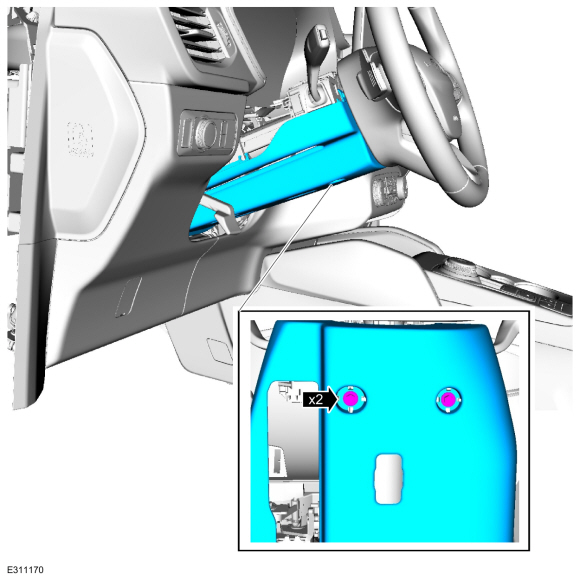
Remove the bolts and the lower steering column shroud.
Torque:
17 lb.in (1.9 Nm)
-
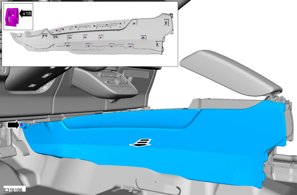
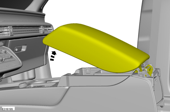
Release the clips and remove the LH instrument panel end cap.
-
-
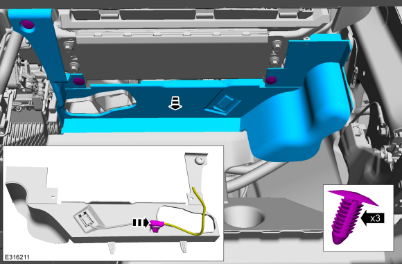
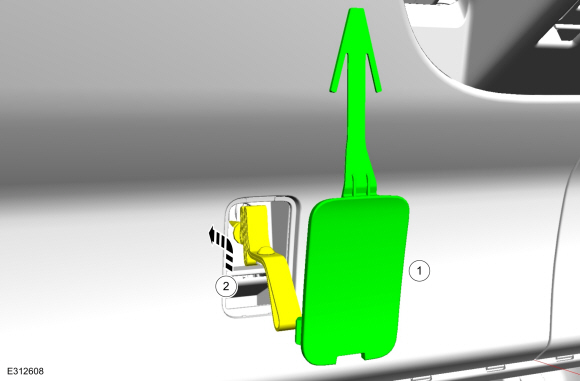
Remove the cover.
-
Lift the cable and strap upward and reward to disengage from the lower trim panel.
-
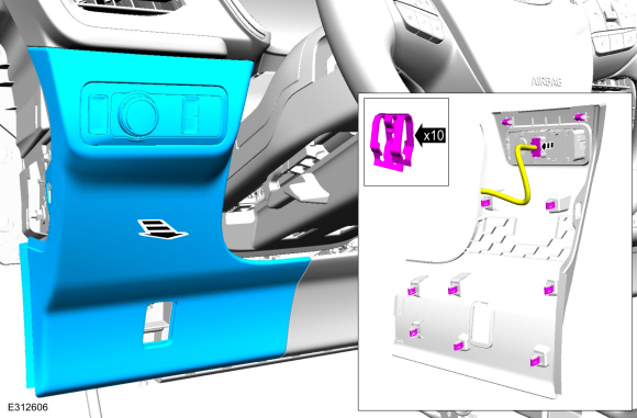
Release the clips and remove the LH trim panel.
-
Disconnect the electrical connector.
-
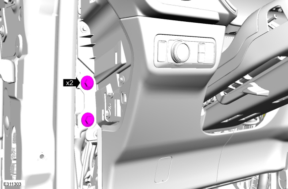
Remove the bolts.
Torque:
35 lb.ft (48 Nm)
-
Remove the accelerator pedal.
Refer to: Accelerator Pedal (310-02)
.
-
NOTICE:
Do not service the brake pedal or brake booster
without first removing the stoplamp switch. The switch must be removed
with the brake pedal in the at-rest position. The switch plunger must be
compressed for the switch to rotate in the bracket. Attempting to
remove the switch when the plunger is extended (during pedal apply) will
result in damage to the switch.
Remove the stoplamp switch.
Refer to: Stoplamp Switch (417-01 Exterior Lighting, Removal and Installation).
-
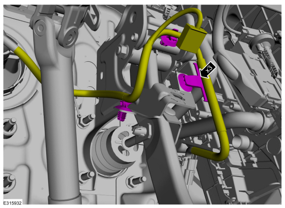
Detach the harness retainers and position the wiring aside.
-
Remove and discard the clevis pin.
-
Remove the 5 brake pedal bracket nuts.
-
NOTE:
Have an assistant to pull the HCU away from the cowl enough to allow the brake pedal bracket to clear the studs.
-
Pull the LH side of the instrument panel away from the cowl slightly.
-
Remove the brake pedal and bracket.
Installation
-
NOTICE:
Do not press, pull or otherwise move the brake pedal
while installing the stoplamp switch. The switch must be installed with
the booster push rod attached to the brake pedal and with the brake
pedal in the at-rest position. Installing the switch with the brake
pedal in any other position will result in incorrect adjustment and may
damage the switch.
To install, reverse the removal procedure.
-
Install the nuts in sequence shown.
Torque:
18 lb.ft (25 Nm)
Removal
NOTICE:
If the fluid is spilled on the paintwork, the affected area must be immediately washed down with cold water.
NOTE:
Removal steps in this procedure may contain installation details...
Removal
NOTE:
Removal steps in this procedure may contain installation details.
Remove the cowl panel grille
Refer to: Cowl Panel Grille (501-02 Front End Body Panels, Removal and Installation)...
Other information:
Insulation
WARNING:
To prevent the risk of high-voltage shock, always follow
precisely all warnings and service instructions, including instructions
to depower the system. The high-voltage system utilizes approximately
300 volts DC, provided through high-voltage cables to its components and
modules...
Special Tool(s) /
General Equipment
Interior Trim Remover
Removal
NOTE:
Removal steps in this procedure may contain installation details.
Open the rear tail gate.
Release the clips and remove the upper liftgate trim panel...

 Removal and Installation - Brake Master Cylinder - Vehicles With: Vacuum Brake Booster
 Removal and Installation - Brake Pedal and Bracket - Vehicles With: Electric Brake Booster