Ford Escape 2020-2026 Service Manual / Powertrain / Engine / Electronic Engine Controls / Removal and Installation - Camshaft Position (CMP) Sensor
Ford Escape: Electronic Engine Controls / Removal and Installation - Camshaft Position (CMP) Sensor
Materials
| Name | Specification |
|---|---|
| Motorcraft® Silicone Brake Caliper Grease and Dielectric Compound XG-3-A |
ESA-M1C200-A ESE-M1C171-A |
Removal
NOTE: Removal steps in this procedure may contain installation details.
-
NOTICE: Do not pull the engine appearance cover forward or sideways to remove. Failure to press straight upward on the underside of the cover at the attachment points may result in damage to the cover or engine components.
-
Remove the engine appearance cover nut.
-
Place your hand under the engine appearance cover at
each grommet location and pull straight up to release each grommet from
the studs.
-
After all of the grommets have been released from the studs, remove the appearance cover from the engine.
-
Remove the engine appearance cover nut.
 |
-
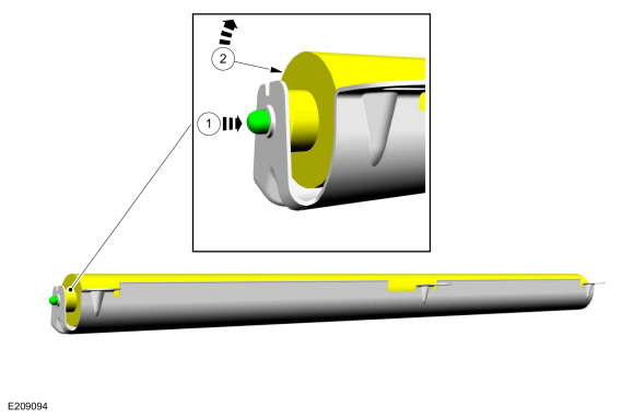
NOTE: Lubricate the O-ring seal with the clean engine oil.
NOTE: The O-ring seal is to be reused unless damaged.
Disconnect the CMP sensor electrical connector. Remove the bolt and the CMP sensor
Torque: 53 lb.in (6 Nm)
 |
Installation
-
To install, reverse the removal procedure.
-
-
NOTE: Lubricating the grommets with silicone grease will aid in the installation of the engine appearance cover, and any future removal and installation of the cover.
Lubricate each grommet with silicone grease.
Material: Motorcraft® Silicone Brake Caliper Grease and Dielectric Compound / XG-3-A (ESA-M1C200-A) (ESE-M1C171-A)
-
Position the engine appearance cover onto engine with the grommets aligned with the studs.
-
Press down on the engine appearance cover at each grommet location to attach the grommets onto the studs.
-
Install the engine appearance cover nut.
Torque: 44 lb.in (5 Nm)
-
If the engine appearance cover stud bolt is loosened
or removed, it must be installed/tightened into the valve cover.
Torque: 62 lb.in (7 Nm)
-
|
 Diagnosis and Testing - Variable Camshaft Timing (VCT) System
Diagnostic Trouble Code (DTC) Chart
Diagnostics in this manual assume a certain skill level and knowledge of Ford-specific diagnostic practices.REFER to: Diagnostic Methods (100-00 General Information, Description and Operation)...
 Removal and Installation - Catalyst Monitor Sensor
Special Tool(s) /
General Equipment
303-476
(T94P-9472-A)
Socket, Exhaust Gas Oxygen SensorTKIT-1994-LM/MTKIT-1994-FTKIT-1994-FLM/FM
Materials
Name
Specification
Motorcraft® High Temperature Nickel Anti-Seize LubricantXL-2
-
Motorcraft® Penetrating and Lock LubricantXL-1
-
Motorcraft® Silicone Brake Caliper Grease and Dielectric CompoundXG-3-A
..
Other information:
Ford Escape 2020-2026 Owners Manual: Using Summer Tires. Using Snow Chains
Using Summer Tires Summer tires provide superior performance on wet and dry roads. Summer tires do not have the Mud and Snow (M+S or M/S) tire traction rating on the tire side wall. Since summer tires do not have the same traction performance as All-season or Snow tires, we do not recommend using summer tires when temperatures drop to about 45°F (7°C) or below, depending on tire wear an..
Ford Escape 2020-2026 Owners Manual: Brakes – Troubleshooting
Brakes – Warning Lamps If the ABS indicator illuminates when you are driving, this indicates a malfunction. Your vehicle continues to have normal braking without the anti-lock braking system function. See an authorized dealer. It also momentarily illuminates when you switch the ignition on to confirm the lamp is functional. If it does not illuminate when you switch the ignition on, or b..
Categories
- Manuals Home
- 4th Generation Ford Escape Owners Manual
- 4th Generation Ford Escape Service Manual
- All-Wheel Drive
- What Is the Tire Pressure Monitoring System. Tire Pressure Monitoring System Overview
- Opening and Closing the Hood
- New on site
- Most important about car
Vehicle Identification
Locating the Vehicle Identification Number
The vehicle identification number is on the left-hand side of the instrument panel.

Copyright © 2026 www.fordescape4.com