Ford Escape: Exhaust System / Removal and Installation - Catalytic Converter
Special Tool(s) /
General Equipment
Removal
NOTE:
If the catalytic converter is not being replaced, the HO2S
and the catalyst monitor sensor do not need to be removed from the
catalytic converter. Disconnecting the electrical connectors is still
necessary.
NOTE:
Removal steps in this procedure may contain installation details.
-
With the vehicle in NEUTRAL, position it on a hoist.
Refer to: Jacking and Lifting - Overview (100-02 Jacking and Lifting, Description and Operation).
-
Remove the HO2S .
Refer to: Heated Oxygen Sensor (HO2S) (303-14C Electronic Engine Controls, Removal and Installation).
-
Remove the catalyst monitor sensor.
Refer to: Catalyst Monitor Sensor (303-14C Electronic Engine Controls, Removal and Installation).
-
Remove the EGR cooler inlet tube.
Refer to: Exhaust Gas Recirculation (EGR) Cooler Inlet Tube (303-08C Engine Emission Control, Removal and Installation).
-
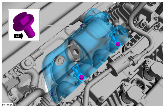
Remove the bolts and the heat shield.
Torque:
97 lb.in (11 Nm)
-
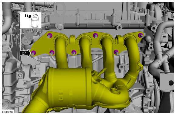
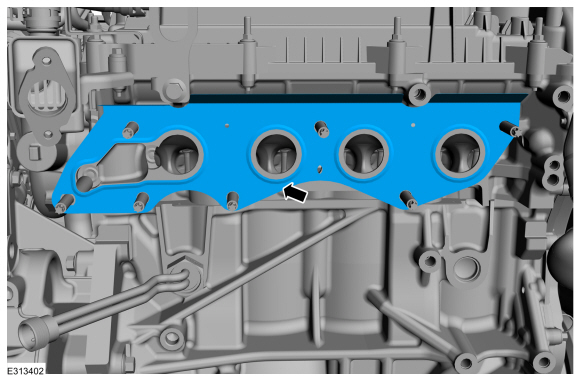
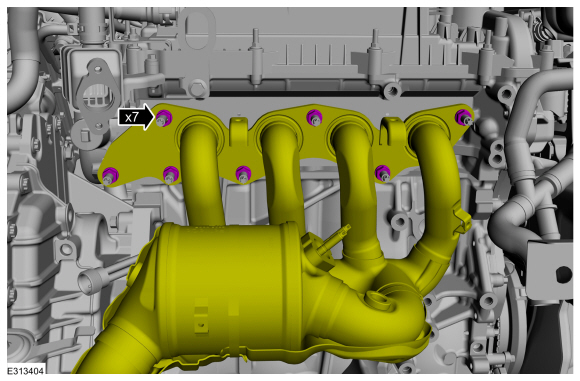
Remove and discard the exhaust manifold nuts.
-
Remove the muffler and tailpipe.
Refer to: Muffler and Tailpipe - Plug-In Hybrid Electric Vehicle (PHEV) (309-00C Exhaust System, Removal and Installation).
Refer to: Muffler and Tailpipe - Full Hybrid Electric Vehicle (FHEV) (309-00C Exhaust System, Removal and Installation).
-
Remove the engine front undershield.
Refer to: Engine Front Undershield (501-02 Front End Body Panels, Removal and Installation).
-
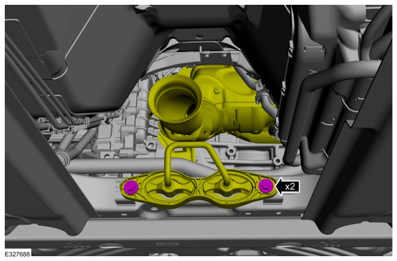
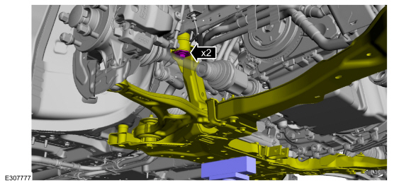
Remove the catalytic converter support bracket bolts.
Torque:
18 lb.ft (25 Nm)
-
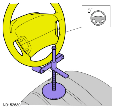
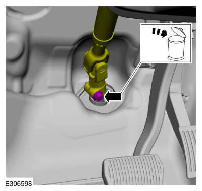
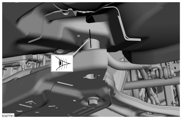
Using a holding device, hold the steering wheel in the straight-ahead position.
-
-
Remove the bolt and discard.
-
Position steering column shaft aside.
Torque:
46 lb.ft (63 Nm)
-
If equipped.
Remove the bolts and the shield.
-
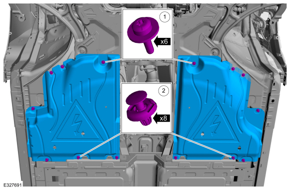
-
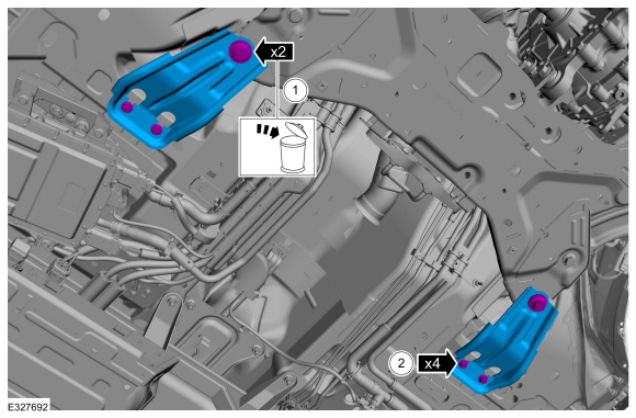
Remove the screws.
-
Remove the push pins and the underbody deflector shield.
-
Remove the front bumper cover.
Refer to: Front Bumper Cover (501-19 Bumpers, Removal and Installation).
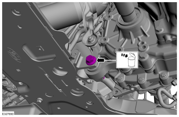
-
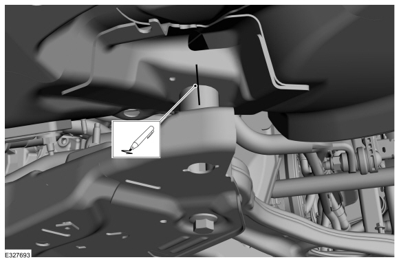
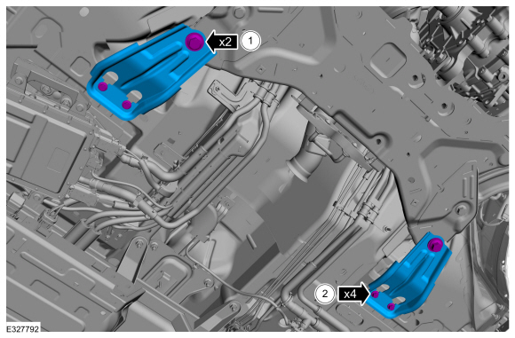
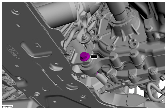
Remove and discard the roll restrictor bracket bolt.
-
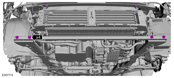
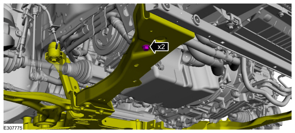
Remove the subframe support bracket bolts.
-
-
Remove and discard the rearward subframe bolts.
-
Remove the bolts and the subframe brackets.
-
On both sides, index-mark the subframe to the body.
-
On both sides, remove the front subframe bolts.
-
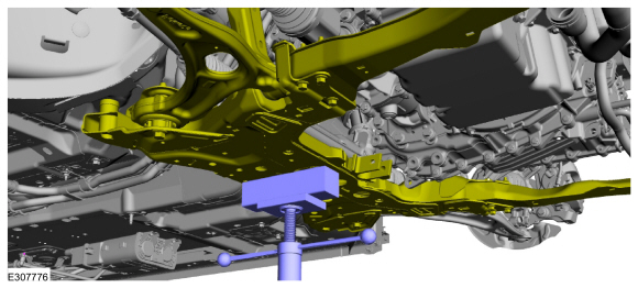
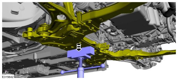
Support the subframe with a screw jack.
Use the General Equipment: Wooden Block
-
On both sides, loosen the subframe bolts.
-
NOTICE:
Care must be taken when lowering the front subframe
to ensure the front subframe mounting structure is not damaged.
NOTE:
Lower the front subframe only enough to allow removal of the catalytic converter assembly.
Using a screw jack, lower the subframe.
-
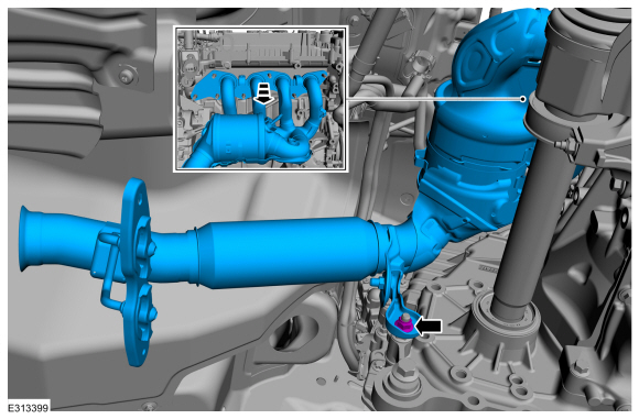
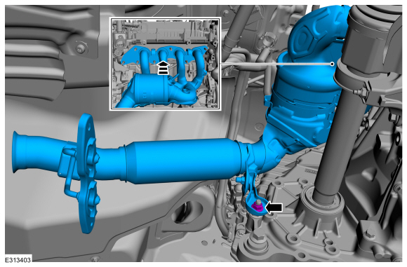
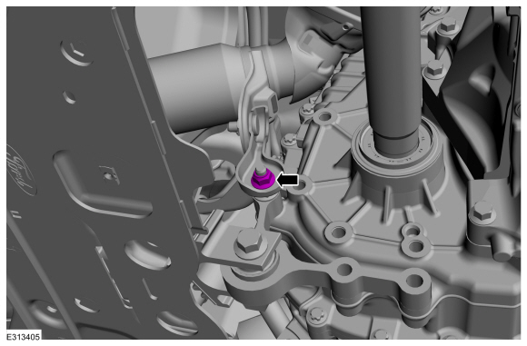
Remove the lower bracket nut and the catalytic converter.
-
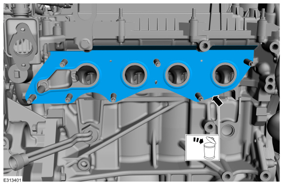
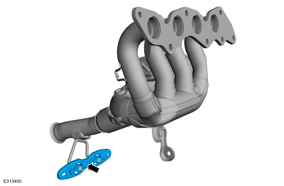
Remove and discard the gasket.
-
NOTE:
The following step is only required if the components are being replaced with new items:
Remove the isolator bracket assembly.
Installation
-
Clean all exhaust connections before reassembly.
-
NOTE:
The following step is only required if the components are being replaced with new items:
Install the isolator bracket assembly.
-
NOTE:
Make sure that new gasket is installed:
Install a new gasket.
-
NOTE:
The lower bracket nut is only finger tight at this step.
Position the catalytic converter in the vehicle and install the lower bracket nut.
-
Raise the front subframe.
-
On both sides, install the front subframe bolts finger tight.
-
NOTE:
Make sure new bolts are used.
-
Install the subframe brackets and the new rearward subframe bolts finger tight.
-
Install the subframe bracket bolts finger tight.
-
On both sides, align index-mark made during removal.
-
On both sides, tighten the subframe bolts.
Torque:
85 lb.ft (115 Nm)
-
On both sides, tighten the front subframe bolts.
Torque:
22 lb.ft (30 Nm)
-
-
Tighten the bolts.
Torque:
Stage 1:
159 lb.ft (215 Nm)
Stage 2:
60°
-
Tighten the bolts.
Torque:
46 lb.ft (63 Nm)
-
Install the subframe support bracket bolts.
Torque:
22 lb.ft (30 Nm)
-
NOTE:
Make sure new bolt is used.
Install a new roll restrictor bolt.
Torque:
129 lb.ft (175 Nm)
-
NOTE:
Make sure that new exhaust manifold nuts are installed:
Install the exhaust manifold nuts.
Torque:
41 lb.ft (55 Nm)
-
Tighten the lower bracket nut.
Torque:
35 lb.ft (48 Nm)
-
To install, reverse the removal procedure.
-
Check the exhaust system for leaks.
Global Customer Symptom Code (GCSC) Chart
Diagnostics in this manual assume a certain skill level and knowledge of Ford-specific diagnostic practices...
Special Tool(s) /
General Equipment
Wooden Block
Removal
NOTE:
If the catalytic converter is not being replaced, the HO2S
and the catalyst monitor sensor do not need to be removed from the
catalytic converter...
Other information:
Draining
With the vehicle in NEUTRAL, position it on a hoist.
Refer to: Jacking and Lifting - Overview (100-02 Jacking and Lifting, Description and Operation).
Remove and discard the RDU fluid fill plug.
Remove and discard the RDU fluid drain plug and allow the RDU fluid to drain...
Vehicles Sold in the United States: Getting Roadside Assistance
To fully assist you should you have a
vehicle concern, Ford Motor Company
offers a complimentary roadside
assistance program. This program is
separate from the New Vehicle Limited
Warranty...
.jpg)
.jpg)
.jpg)
 Diagnosis and Testing - Exhaust System
 Removal and Installation - Catalytic Converter - Hybrid Electric Vehicle (HEV), FWD