Ford Escape 2020-2026 Service Manual / Powertrain / Engine / Electronic Engine Controls / Removal and Installation - Cylinder Head Temperature (CHT) Sensor
Ford Escape: Electronic Engine Controls / Removal and Installation - Cylinder Head Temperature (CHT) Sensor
Materials
| Name | Specification |
|---|---|
| Motorcraft® Silicone Brake Caliper Grease and Dielectric Compound XG-3-A |
ESA-M1C200-A ESE-M1C171-A |
Removal
NOTE: Removal steps in this procedure may contain installation details.
-
NOTICE: Do not pull the engine appearance cover forward or sideways to remove. Failure to press straight upward on the underside of the cover at the attachment points may result in damage to the cover or engine components.
-
Remove the engine appearance cover nut.
-
Place your hand under the engine appearance cover at
each grommet location and pull straight up to release each grommet from
the studs.
-
After all of the grommets have been released from the studs, remove the appearance cover from the engine.
-
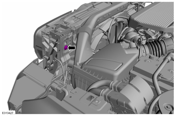
Remove the engine appearance cover nut.
 |
-
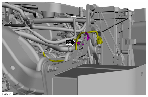
Remove the cover and disconnect the CHT sensor electrical connector.
 |
-
NOTE: Install a new CHT sensor.
Remove and discard the CHT sensor.
Torque: 106 lb.in (12 Nm)
 |
Installation
-
To install, reverse the removal procedure.
-
-
NOTE: Lubricating the grommets with silicone grease will aid in the installation of the engine appearance cover, and any future removal and installation of the cover.
Lubricate each grommet with silicone grease.
Material: Motorcraft® Silicone Brake Caliper Grease and Dielectric Compound / XG-3-A (ESA-M1C200-A) (ESE-M1C171-A)
-
Position the engine appearance cover onto engine with the grommets aligned with the studs.
-
Press down on the engine appearance cover at each grommet location to attach the grommets onto the studs.
-
Install the engine appearance cover nut.
Torque: 44 lb.in (5 Nm)
-
If the engine appearance cover stud bolt is loosened
or removed, it must be installed/tightened into the valve cover.
Torque: 62 lb.in (7 Nm)
-
|
 Removal and Installation - Crankshaft Position (CKP) Sensor
Special Tool(s) /
General Equipment
303-1699Tool, Crank Sensor Alignment
303-507Timing Peg, Crankshaft TDCTKIT-2001N-FLMTKIT-2001N-ROW
Ford Diagnostic Equipment
Removal
NOTICE:
During engine repair procedures, cleanliness is extremely
important...
 Removal and Installation - Engine Coolant Temperature (ECT) Sensor
Special Tool(s) /
General Equipment
Locking Pliers
Materials
Name
Specification
Motorcraft® Orange Concentrated Antifreeze/CoolantVC-3-B
WSS-M97B44-D
Removal
NOTE:
Removal steps in this procedure may contain installation details...
Other information:
Ford Escape 2020-2026 Service Manual: Description and Operation - Parking Aid - Overview
Overview - Active Park Assist The active park assist system is a full-assisted parking system. The system assists parking into and out (assist out of parking spots only available for parallel parking) of parking spaces. Sensors are used to detect parking spaces...
Ford Escape 2020-2026 Service Manual: Removal and Installation - Cowl Panel Grille
Removal NOTE: Removal steps in this procedure may contain installation details. Remove the windshield wiper pivot arm. Refer to: Windshield Wiper Pivot Arm (501-16 Wipers and Washers, Removal and Installation). Remove the clips...
Categories
- Manuals Home
- 4th Generation Ford Escape Owners Manual
- 4th Generation Ford Escape Service Manual
- General Procedures - Brake Service Mode Activation and Deactivation
- Drive Modes
- Switching the Lane Keeping System On and Off. Switching the Lane Keeping System Mode. Alert Mode
- New on site
- Most important about car
Fastening the Seatbelts

Copyright © 2026 www.fordescape4.com