Ford Escape: Engine / Removal and Installation - Crankshaft Pulley
Special Tool(s) /
General Equipment
 |
303-1416
Tool, Crank Damper Holding
TKIT-2008ET-FLM |
.jpg) |
303-1699
Tool, Crank Sensor Alignment |
 |
303-465
Tool, Camshaft Align Timing
TKIT-1994-LMH/MH2
TKIT-1994-FH/FMH/FLMH |
.jpg) |
303-507
Timing Peg, Crankshaft TDC
TKIT-2001N-FLM
TKIT-2001N-ROW |
| Trolley Jack |
| Wooden Block |
Removal
NOTICE:
Do not loosen or remove the crankshaft pulley bolt without
first installing the special tools as instructed in this procedure. The
crankshaft pulley and the crankshaft timing sprocket are not keyed to
the crankshaft. The crankshaft, the crankshaft sprocket and the pulley
are fitted together by friction. For that reason, the crankshaft
sprocket is also unfastened if the pulley bolt is loosened. Before any
repair requiring loosening or removal of the crankshaft pulley bolt, the
crankshaft and camshafts must be locked in place by the special service
tools, otherwise severe engine damage can occur.
NOTICE:
During engine repair procedures, cleanliness is extremely
important. All parts must be thoroughly cleaned and any foreign
material, including any material created while cleaning gasket surfaces,
that enters the oil passages, coolant passages or the oil pan, can
cause engine failure.
-
Remove the RHF fender splash shield.
Refer to: Fender Splash Shield (501-02 Front End Body Panels, Removal and Installation).
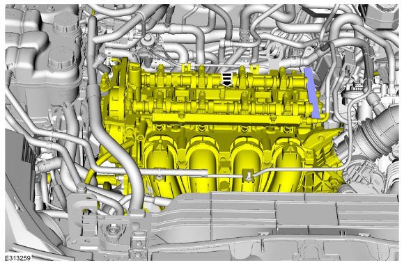
-
Remove the valve cover.
Refer to: Valve Cover (303-01C Engine, Removal and Installation).
-
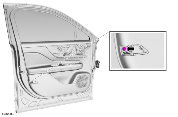
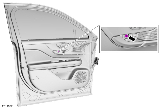
Remove the bolts and the CKP sensor.
-
Release the tabs and remove the crankshaft pulley cover.
-
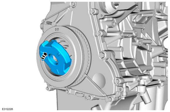
NOTE:
Failure to position the No. 1 piston at TDC can result in damage to the
engine. Turn the engine in the normal direction of rotation only.
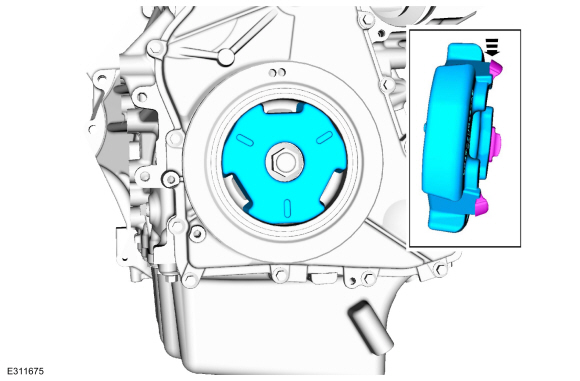
Using the crankshaft pulley bolt, turn the crankshaft clockwise to position the No. 1 piston at TDC .
-
The hole in the crankshaft pulley should be in the 6 o'clock position.
-
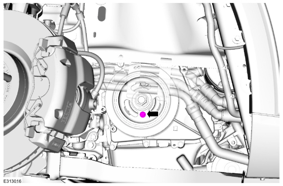
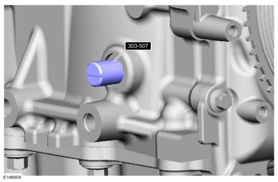
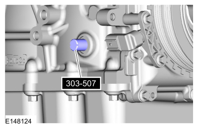
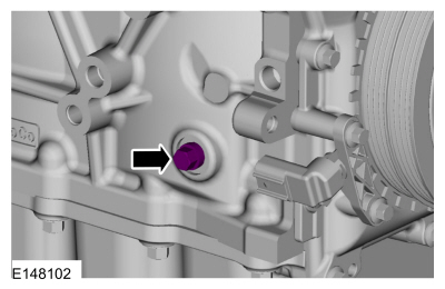
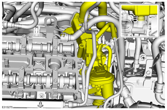
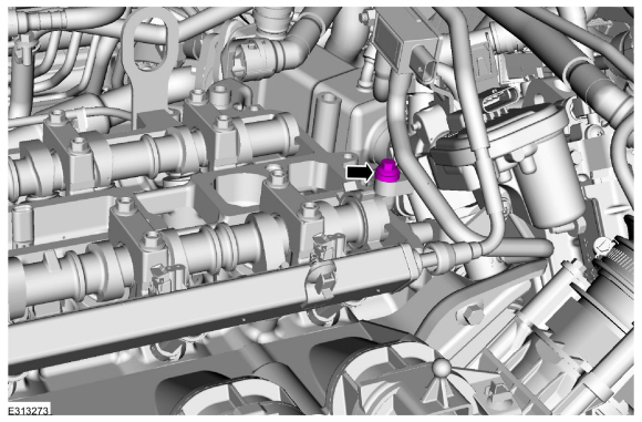
Remove the engine plug bolt.
-
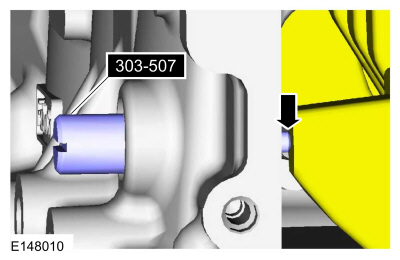
NOTE:
The Crankshaft TDC Timing Peg will contact the crankshaft and prevent
it from turning past TDC . However, the crankshaft can still be rotated
in the counterclockwise direction. The crankshaft must remain at the TDC
position during disassembly.
-
Install Special Service Tool: 303-507
Timing Peg, Crankshaft TDC.
-
Rotate the crankshaft slowly clockwise until the crankshaft balance
weight is up against the Crankshaft TDC Timing Peg. The engine is now at
TDC .
-
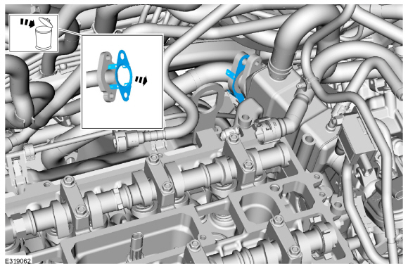
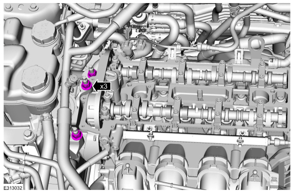
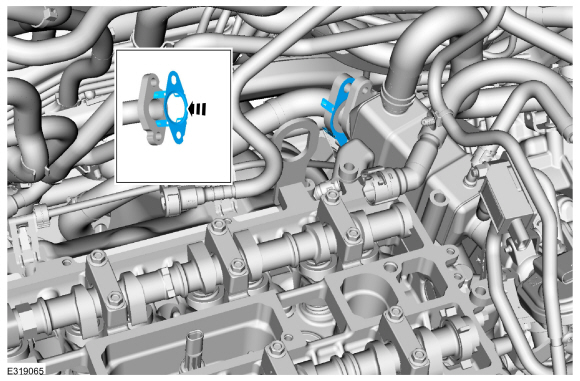
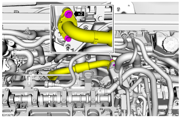
Remove the bolts and position the EGR cooler inlet tube aside.
-
Remove and discard the EGR cooler inlet tube gasket.
-
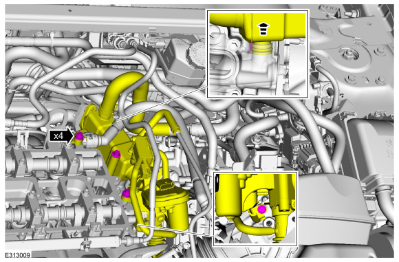
Remove the bolts and position the EGR cooler aside.
-
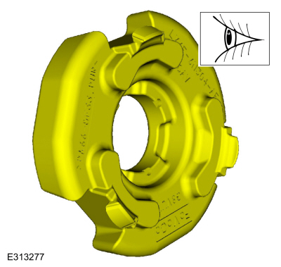
NOTE:
The Camshaft Alignment Plate is for camshaft
alignment only. Using this tool to prevent engine rotation can result in
engine damage.
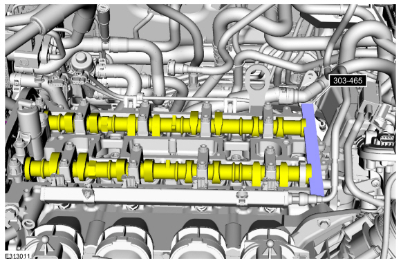
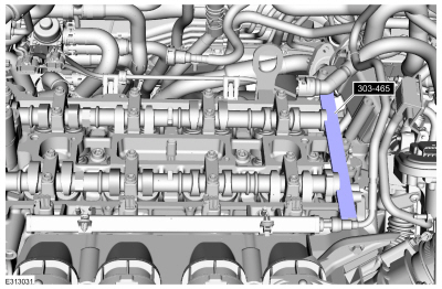
NOTE:
The camshaft timing slots are offset. If the
Camshaft Alignment Plate cannot be installed, rotate the crankshaft one
complete revolution clockwise to correctly position the camshafts.
Install Special Service Tool: 303-465
Tool, Camshaft Align Timing.
-
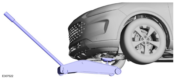
Position the jack and wooden block under the front of the oil pan to support the engine.
Use the General Equipment: Trolley Jack
Use the General Equipment: Wooden Block
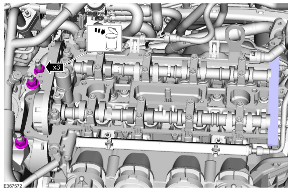
-
Remove and discard the engine mount nuts.
-
Lower the engine 88.9 mm ( 3.5 inches ).
-
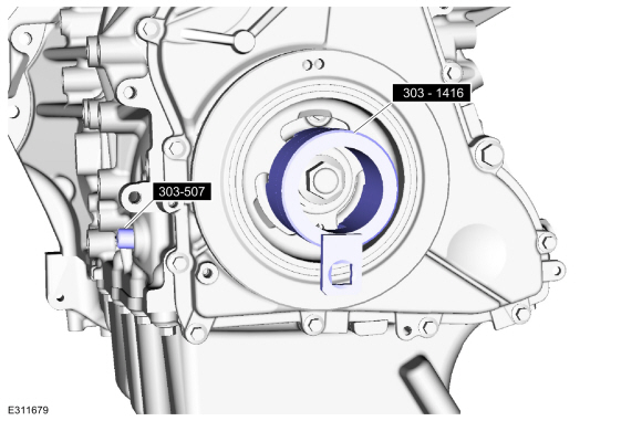
Install Suggested Tool: 303-1416
Tool, Crank Damper Holding. Tool shown or a commercially available equivalent can be used.
Use Special Service Tool: 303-507
Timing Peg, Crankshaft TDC.
-
NOTE:
The crankshaft must remain in the TDC
position during removal of the pulley bolt or damage to the engine can
occur. Therefore, the crankshaft pulley must be held in place with the
Crankshaft Damper Holding Tool, and the bolt should be removed using an
air impact wrench (1/2-in drive minimum).
NOTE:
If equipped, the crankshaft sprocket diamond washer may come off with the crankshaft pulley.
NOTE:
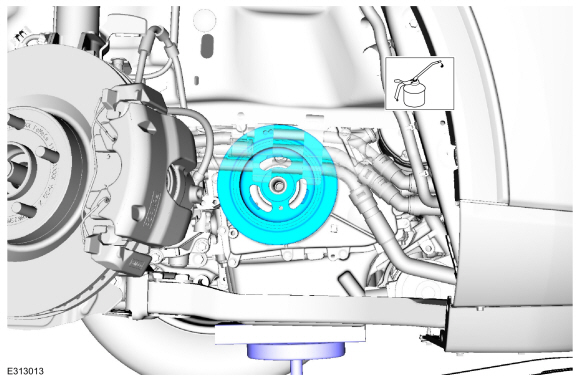
Use an air impact wrench to remove the crankshaft pulley bolt.
Use the Crankshaft Damper Holding Tool and a suitable
1/2-in drive hand tool to hold the crankshaft pulley. Use an air impact
wrench to remove the crankshaft pulley bolt.
-
Remove and discard the crankshaft pulley bolt and washer.
-
Remove the crankshaft pulley.
Use Special Service Tool: 303-1416
Tool, Crank Damper Holding.
Installation
-
NOTE:
Do not install the crankshaft pulley bolt at this time.
NOTE:
Component(s) must be lubricated with clean engine oil.
Lubricate the crankshaft pulley oil sealing surface with clean engine oil and install the crankshaft pulley.
Refer to: Specifications (303-01C Engine, Specifications).
-
NOTE:
Only hand-tighten the 6 mm x 18 mm bolt or damage to the front cover can occur.
NOTE:
This step will correctly align the crankshaft pulley to the crankshaft.
Install an M6 bolt.
-
NOTE:
The crankshaft must remain in the TDC
position during installation of the pulley bolt or damage to the
engine can occur. Therefore, the crankshaft pulley must be held in place
with the Crankshaft Damper Holding Tool and the bolt should be
installed using hand tools only.
NOTE:
Install a new crankshaft pulley bolt.
-
Install a new crankshaft pulley bolt. Use the
Crankshaft Damper Holding tool and a suitable 1/2-in drive hand tool to
hold the crankshaft pulley.
-
Tighten the crankshaft pulley bolt in 2 stages.
Use Special Service Tool: 303-1416
Tool, Crank Damper Holding.
Torque:
Stage 1:
74 lb.ft (100 Nm)
Stage 2:
90 °
-
Remove the M6 bolt.
-
Remove Special Service Tool: 303-507
Timing Peg, Crankshaft TDC.
-
Remove Special Service Tool: 303-465
Tool, Camshaft Align Timing.
-
NOTE:
Only turn the engine in the normal direction of rotation.
Turn the crankshaft clockwise one and three-fourth turns.
-
NOTE:
Only turn the engine in the normal direction of rotation.
Install Special Service Tool: 303-507
Timing Peg, Crankshaft TDC.
-
NOTE:
Only hand-tighten the bolt or damage to the front cover can occur.
Install an M6 bolt, check the position of the crankshaft pulley.
-
If it is not possible to install the bolt, the
engine valve timing must be corrected by repeating this procedure.
-
NOTE:
The Camshaft Alignment Plate is for camshaft
alignment only. Using this tool to prevent engine rotation can result in
engine damage.
NOTE:
If it is not possible to install the Camshaft Alignment Plate, the engine valve timing must be corrected.
Install Special Service Tool: 303-465
Tool, Camshaft Align Timing.
-
Remove Special Service Tool: 303-465
Tool, Camshaft Align Timing.
-
Remove the M6 bolt.
-
NOTE:
Only tighten the bolts finger tight at this stage.
Install the CKP sensor and the bolts.
-
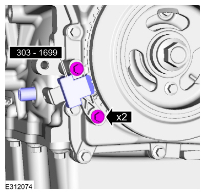
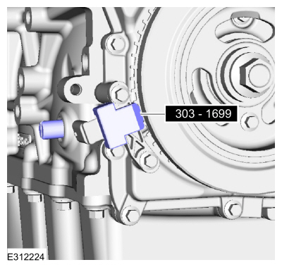
If the special service tool mark does not align with the TDC marked
tooth on the crankshaft pulley, loosen the CKP sensor bolts and adjust
the sensor until the tool is installed then tighten.
Use Suggested Tool: 303-1699
Tool, Crank Sensor Alignment. Tool shown or a commercially available equivalent can be used.
Torque:
62 lb.in (7 Nm)
-
Remove Special Service Tool: 303-1699
Tool, Crank Sensor Alignment.
-
Remove Special Service Tool: 303-507
Timing Peg, Crankshaft TDC.
-
Install the engine plug bolt.
Torque:
177 lb.in (20 Nm)
-
Inspect the crankshaft pulley cover tabs for damage replace if necessary.
-
Install the crankshaft pulley cover.
-
Raise the engine.
-
Install the new engine mount nuts.
Torque:
81 lb.ft (110 Nm)
-
Remove the jack and wooden block from under the engine.
Use the General Equipment: Trolley Jack
Use the General Equipment: Wooden Block
-
Inspect the EGR cooler O-ring seal replace if necessary.
-
NOTE:
Component(s) must be lubricated with clean engine oil.
Lubricate the new EGR cooler O-ring with a small amount of engine oil.
-
Position back the EGR cooler.
Torque:
89 lb.in (10 Nm)
-
Install the EGR assembly bolt and hand tighten the bolt at this stage.
-
Install the EGR assembly mounting bolt.
Torque:
89 lb.in (10 Nm)
-
Install the EGR assembly bolts and hand tighten the bolts at this stage.
-
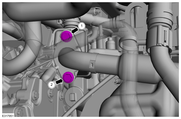
Tighten in the sequence shown.
Torque:
1:
89 lb.in (10 Nm)
2:
89 lb.in (10 Nm)
3:
18 lb.ft (25 Nm)
-
This step only necessary if the water outlet housing was removed or loosened.
Tighten in the sequence shown.
Torque:
Stage 1:
89 lb.in (10 Nm)
Stage 2:
45°
-
Install the new EGR cooler inlet tube gasket.
-
Position back the EGR cooler inlet tube and install the bolts hand tight.
Torque:
22 lb.ft (30 Nm)
-
Tighten in the sequence shown.
Torque:
1:
89 lb.in (10 Nm)
2:
18 lb.ft (24 Nm)
1:
18 lb.ft (24 Nm)
-
Install the valve cover.
Refer to: Valve Cover (303-01C Engine, Removal and Installation).
-
Install the RHF fender splash shield.
Refer to: Fender Splash Shield (501-02 Front End Body Panels, Removal and Installation).
-
After completing repairs, perform the Misfire Monitor
Neutral Profile Correction procedure using a diagnostic scan tool.
Special Tool(s) /
General Equipment
303-096
(T74P-6150-A)
Installer, Camshaft Front Oil SealTKIT-2009TC-F
303-409
(T92C-6700-CH)
Remover, Crankshaft SealTKIT-1992-FH/FMH/FLMHTKIT-1993-LMH/MH
303-507Timing Peg, Crankshaft TDCTKIT-2001N-FLMTKIT-2001N-ROW
Removal
Remove the crankshaft pulley...
Special Tool(s) /
General Equipment
303-328
(T88P-6701-B1)
Replacer, Rear SealTKIT-1988-FLMTKIT-1988-FTKIT-1988-LM
Plastic Scraper
Materials
Name
Specification
Motorcraft® High Performance Engine RTV SiliconeTA-357
WSE-M4G323-A6
Motorcraft® Silicone Gasket RemoverZC-30-A, AZC-30-C
-
Motorcraft® Metal Surface Prep WipesZC-31-B
-
..
Other information:
General Specifications
Item
Specification
Normal engine cranking speed (Average)
200-300 Revolutions Per Minute (RPM)
Starting circuit maximum voltage drop (Engine at normal operating temperature) (Average)
0.5 volt
Starter motor maximum load current draw
900 amps
Starter motor no-load current draw (Av..
Follow these steps to set a preferred
charge time for a charging location.
Select Charge Preferences on the
Charge Settings screen.
Select Charge Time Setup on the Edit
Charge Preferences screen.
Select Add New Location on the
Charge Times screen. You can also edit
settings for previously saved locations
from this screen.
Select an address from the Recent
Charge Locations screen...
.jpg)
.jpg)
.jpg)

.jpg)
.jpg)
.jpg)

.jpg)
.jpg)
.jpg)
.jpg)
.jpg)
.jpg)
 Removal and Installation - Crankshaft Front Seal
 Removal and Installation - Crankshaft Rear Seal