
Ford Escape 2020-2026 Service Manual / Chassis / Driveline / Rear Drive Axle/Differential / Removal and Installation - Drive Pinion Seal
Ford Escape: Rear Drive Axle/Differential / Removal and Installation - Drive Pinion Seal
Special Tool(s) / General Equipment
 |
205-208
(T83T-4676-A)
Installer, Drive Pinion Oil Seal TKIT-1983-F TKIT-1983-FLM TKIT-1983-FX |
| Flat Headed Screw Driver | |
Materials
| Name | Specification |
|---|---|
| Motorcraft® Premium Long-Life Grease XG-1-E1 |
ESA-M1C75-B |
Removal
-
Remove the drive pinion flange.
Refer to: Drive Pinion Flange (205-02 Rear Drive Axle/Differential, Removal and Installation).
-
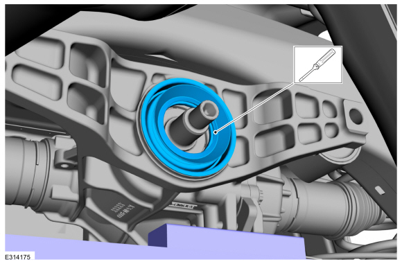
Using a general equipment, remove and replace the drive pinion seal.
Use the General Equipment: Flat Headed Screw Driver
 |
-
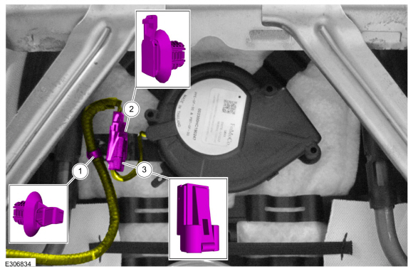
Clean and inspect the drive pinion and pinion seal mating surface.
 |
Installation
-
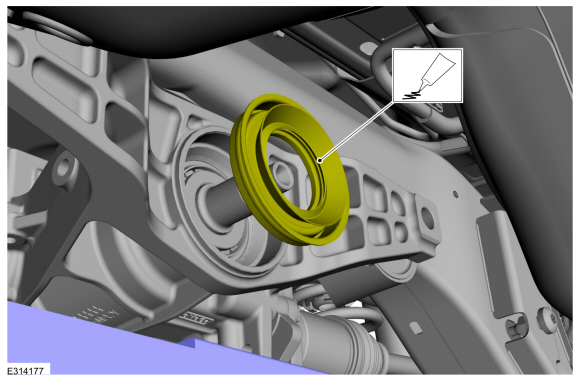
Lubricate the new drive pinion seal lip with grease.
Material: Motorcraft® Premium Long-Life Grease / XG-1-E1 (ESA-M1C75-B)
 |
-
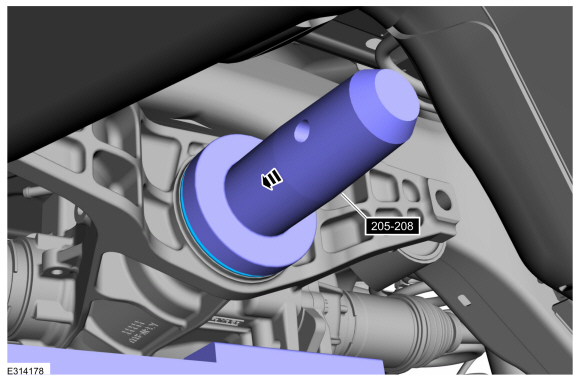
Using the special tool, install the new drive pinion seal.
Use Special Service Tool: 205-208 (T83T-4676-A) Installer, Drive Pinion Oil Seal.
 |
-
Install the drive pinion flange.
Refer to: Drive Pinion Flange (205-02 Rear Drive Axle/Differential, Removal and Installation).

 Removal and Installation - Rear Drive Unit (RDU) Actuator Motor
Removal
Remove the rear axle assembly.
Refer to: Axle Assembly (205-02A)
.
NOTICE:
The RDU contains axle fluid. To prevent spillage, do not tilt the RDU during actuator motor removal or installation...
Other information:
Ford Escape 2020-2026 Service Manual: Removal and Installation - Trailer Module (TRM)
Removal NOTE: Removal steps in this procedure may contain installation details. NOTE: This step is only necessary if the TRM (trailer module) is being replaced. Using a diagnostic scan tool, begin the PMI process for the TRM following the on-screen instructions...
Ford Escape 2020-2026 Service Manual: Description and Operation - Power Brake System - Vehicles With: Electric Brake Booster - System Operation and Component Description
System Operation System Diagram - Electric Brake Boost E347819 *.sttxt { visibility: hidden; } *.stcallout { visibility: visible; } HS-CAN3 HS-CAN1 HS-CAN2 1 IPC 2 RCM 3 BCM 4 PCM 5 GWM ..
Categories
- Manuals Home
- 4th Generation Ford Escape Owners Manual
- 4th Generation Ford Escape Service Manual
- Opening and Closing the Hood
- Power Outlet - Vehicles With: 12V Power Outlet
- Electric Parking Brake
- New on site
- Most important about car
Symbols Glossary
These are some of the symbols you may see on your vehicle.
 Air conditioning system

Copyright © 2026 www.fordescape4.com