Ford Escape 2020-2024 Service Manual / Chassis / Brake System / Anti-Lock Brake System (ABS) and Stability Control / Removal and Installation - Electric Brake Booster (EBB) - Full
Hybrid Electric Vehicle (FHEV)/Plug-In Hybrid Electric Vehicle (PHEV)
Ford Escape: Anti-Lock Brake System (ABS) and Stability Control / Removal and Installation - Electric Brake Booster (EBB) - Full Hybrid Electric Vehicle (FHEV)/Plug-In Hybrid Electric Vehicle (PHEV)
Removal
NOTE: Removal steps in this procedure may contain installation details.
NOTE: The EBB and the ABS module are serviced as an assembly and should not be separated.
-
NOTE: The PMI process must begin with the current ABS module installed. If the current ABS module does not respond to the diagnostic scan tool, the tool may prompt for As-Built Data as part of the repair.
Using a diagnostic scan tool, begin the PMI process for the ABS module following the onscreen instructions.
-
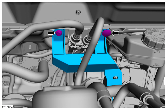
Detach the coolant hose retainers and position the coolant hoses aside.
 |
-
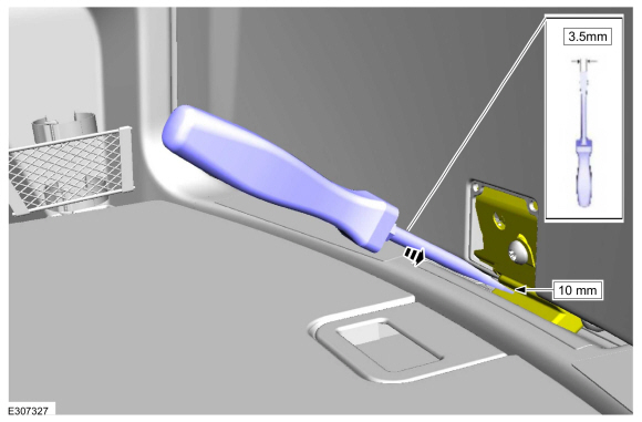
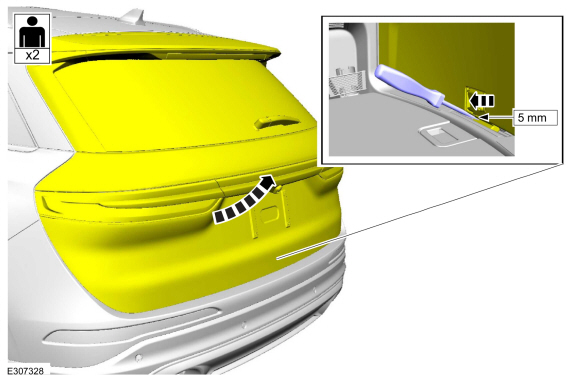
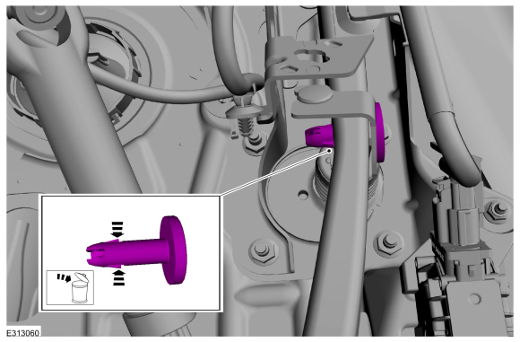
Remove the bolt, the pin-type retainer and the bracket.
Torque: 80 lb.in (9 Nm)
 |
-
Remove the DCDC .
Refer to: Direct Current/Direct Current (DC/DC) Converter Control Module (414-05 Voltage Converter/Inverter, Removal and Installation).
-
Disconnect the electrical connectors.
 |
-
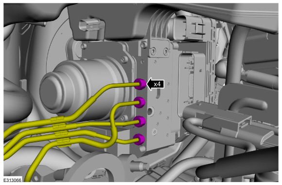
NOTICE: If the brake fluid is spilled on any component, the affected area must be immediately washed down with cold water.
NOTE: Make sure that all openings are sealed.
Disconnect the brake tube fittings.
Torque: 159 lb.in (18 Nm)
 |
-
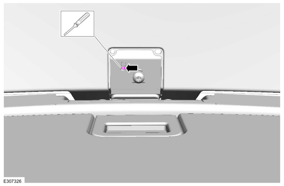
Remove the stoplamp switch.
Refer to: Stoplamp Switch (417-01 Exterior Lighting, Removal and Installation).
-
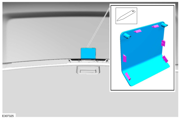
Push inward on the tabs and remove the clevis pin. Discard the pin.
 |
-
Remove the EBB nuts in the order shown.
Torque: 177 lb.in (20 Nm)
 |
-
Remove the the EBB .
 |
Installation
-
To install, reverse the removal procedure.
-
Using a diagnostic scan tool, complete the PMI process for the ABS module following the on-screen instructions.
-
Carry out the following service functions using the scan
tool and following the diagnostic scan tool on-screen instructions.
-
Carry out the ABS Brake System Pressure Bleeding and Bleed Check.
-
Carry out the ABS Calibration.
-
Carry out the EPB initialization.
-
Run the PCM
PATS
programming application and then carry out the Module Initialization
(Parameter Reset) using the scan tool and following the diagnostic scan
tool on-screen instructions.
-
Carry out the ABS Brake System Pressure Bleeding and Bleed Check.
 Removal and Installation - Electric Brake Booster (EBB)
Removal
NOTE:
Removal steps in this procedure may contain installation details.
NOTE:
The EBB and the ABS module are serviced as an assembly and should not be separated...
 Removal and Installation - Front Wheel Speed Sensor
Materials
Name
Specification
Motorcraft® Metal Brake Parts CleanerPM-4-A, PM-4-B, APM-4-C
-
Removal
NOTE:
Removal steps in this procedure may contain installation details...
Other information:
Ford Escape 2020-2024 Service Manual: Removal and Installation - Parking Brake Switch
Special Tool(s) / General Equipment Interior Trim Remover Removal NOTE: Removal steps in this procedure may contain installation details. Release the clips and position aside the floor console upper trim panel. Lift the front of the upper trim panel to release the clips...
Ford Escape 2020-2024 Owners Manual: How Does Cross Traffic Alert Work
Cross Traffic Alert detects vehicles that approach at a speed between 4–37 mph (6–60 km/h). Coverage decreases when the sensors are partially, mostly or fully obstructed. The sensor on the left-hand side is only partially obstructed and zone coverage on the right-hand side is maximized...
Categories
- Manuals Home
- 4th Generation Ford Escape Owners Manual
- 4th Generation Ford Escape Service Manual
- Adjusting the Headlamps
- What Is the Speedometer. Fuel Gauge
- Plug-In Hybrid Electric Vehicle Drive Modes
- New on site
- Most important about car
Sitting in the Correct Position

When you use them properly, the seat, head restraint, seatbelt and airbags will provide optimum protection in the event of a crash.
Copyright © 2024 www.fordescape4.com