Ford Escape 2020-2026 Service Manual / Chassis / Brake System / Anti-Lock Brake System (ABS) and Stability Control / Removal and Installation - Electric Brake Booster (EBB)
Ford Escape: Anti-Lock Brake System (ABS) and Stability Control / Removal and Installation - Electric Brake Booster (EBB)
Removal
NOTE: Removal steps in this procedure may contain installation details.
NOTE: The EBB and the ABS module are serviced as an assembly and should not be separated.
-
NOTE: The PMI process must begin with the current ABS module installed. If the current ABS module does not respond to the diagnostic scan tool, the tool may prompt for As-Built Data as part of the repair.
Using a diagnostic scan tool, begin the PMI process for the ABS module following the onscreen instructions.
-
Remove the battery tray.
Refer to: Battery Tray - 1.5L EcoBoost (132kW/180PS) – I3 (Y1)/2.0L EcoBoost (177kW/240PS) – MI4 (414-01 Battery, Mounting and Cables, Removal and Installation).
-
Disconnect the electrical connectors.
 |
-
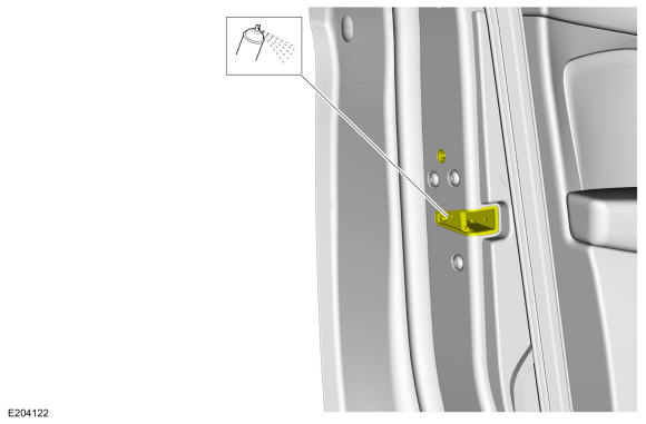
NOTICE: If the brake fluid is spilled on any component, the affected area must be immediately washed down with cold water.
NOTE: Make sure that all openings are sealed.
Disconnect the brake tube fittings.
Torque: 159 lb.in (18 Nm)
 |
-
Remove the stoplamp switch.
Refer to: Stoplamp Switch (417-01 Exterior Lighting, Removal and Installation).
-
Push inward on the tabs and remove the clevis pin. Discard the pin.
 |
-
Remove the EBB nuts in the order shown.
Torque: 177 lb.in (20 Nm)
 |
-
Remove the the EBB .
 |
Installation
-
To install, reverse the removal procedure.
-
Using a diagnostic scan tool, complete the PMI process for the ABS module following the on-screen instructions.
-
Bleed the brake system.
Refer to: Brake System Pressure Bleeding - Vehicles With: Electric Brake Booster (206-00 Brake System - General Information, General Procedures).
-
Carry out the following service functions using the scan
tool and following the diagnostic scan tool on-screen instructions.
-
Carry out the ABS Calibration.
-
Carry out the EPB initialization.
-
Run the PCM
PATS
programming application and then carry out the Module Initialization
(Parameter Reset) using the scan tool and following the diagnostic scan
tool on-screen instructions.
-
Carry out the ABS Calibration.
 Removal and Installation - Anti-Lock Brake System (ABS) Module - Vehicles With: Vacuum Brake Booster
Removal
NOTE:
A new HCU is equipped with an ABS module. A new ABS module does not come equipped with an HCU .
NOTE:
Removal steps in this procedure may contain installation details...
 Removal and Installation - Electric Brake Booster (EBB) - Full
Hybrid Electric Vehicle (FHEV)/Plug-In Hybrid Electric Vehicle (PHEV)
Removal and Installation - Electric Brake Booster (EBB) - Full
Hybrid Electric Vehicle (FHEV)/Plug-In Hybrid Electric Vehicle (PHEV)
Removal
NOTE:
Removal steps in this procedure may contain installation details.
NOTE:
The EBB and the ABS module are serviced as an assembly and should not be separated...
Other information:
Ford Escape 2020-2026 Owners Manual: Creating a Vehicle Wi-Fi Hotspot
You can create a Wi-Fi hotspot in your vehicle and allow devices to connect to it for access to the Internet. Press the button to enter the settings menu. Select Connectivity Features. Select Vehicle Hotspot.Note: The vehicle hotspot default setting is on...
Ford Escape 2020-2026 Service Manual: Removal and Installation - Cooling Fan Motor and Shroud
Removal NOTE: Removal steps in this procedure may contain installation details. With the vehicle in NEUTRAL, position it on a hoist. Refer to: Jacking and Lifting - Overview (100-02 Jacking and Lifting, Description and Operation). Remove the retainers, release the tabs and remove the air cleaner intake duct pipe...
Categories
- Manuals Home
- 4th Generation Ford Escape Owners Manual
- 4th Generation Ford Escape Service Manual
- Description and Operation - Identification Codes
- Symbols Glossary
- Drive Modes
- New on site
- Most important about car
Engine Oil
Engine Oil Dipstick Overview

Copyright © 2026 www.fordescape4.com