Ford Escape 2020-2026 Service Manual / Powertrain / Engine / Electronic Engine Controls / Removal and Installation - Engine Coolant Temperature (ECT) Sensor
Ford Escape: Electronic Engine Controls / Removal and Installation - Engine Coolant Temperature (ECT) Sensor
Special Tool(s) / General Equipment
| Locking Pliers |
Materials
| Name | Specification |
|---|---|
| Motorcraft® Orange Concentrated Antifreeze/Coolant VC-3-B |
WSS-M97B44-D |
Removal
NOTE: Removal steps in this procedure may contain installation details.
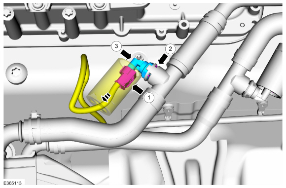
Engine Coolant Temperature (ECT3) Sensor
-
-
Remove the shield and disconnect the electrical connector.
Use the General Equipment: Locking Pliers
-
Remove retaining clip from the ECT ECT3 sensor.
-
Remove the ECT ECT3 sensor.
-
Remove the shield and disconnect the electrical connector.
.jpg) |
Engine Coolant Temperature (ECT4) Sensor
-
-
Remove the shield and disconnect the electrical connector.
Use the General Equipment: Locking Pliers
-
Remove retaining clip from the ECT ECT4 sensor.
-
Remove the ECT ECT4 sensor.
-
Remove the shield and disconnect the electrical connector.
 |
Installation
-
To install, reverse the removal procedure.
-
Check the coolant level in the degas bottle and add coolant as necessary.
Refer to: Engine Cooling System Draining, Vacuum Filling and Bleeding (303-03C Engine Cooling, General Procedures).
Material: Motorcraft® Orange Concentrated Antifreeze/Coolant / VC-3-B (WSS-M97B44-D)
 Removal and Installation - Cylinder Head Temperature (CHT) Sensor
Materials
Name
Specification
Motorcraft® Silicone Brake Caliper Grease and Dielectric CompoundXG-3-A
ESA-M1C200-AESE-M1C171-A
Removal
NOTE:
Removal steps in this procedure may contain installation details...
 Removal and Installation - Heated Oxygen Sensor (HO2S)
Special Tool(s) /
General Equipment
303-476
(T94P-9472-A)
Socket, Exhaust Gas Oxygen SensorTKIT-1994-LM/MTKIT-1994-FTKIT-1994-FLM/FM
Materials
Name
Specification
Motorcraft® High Temperature Nickel Anti-Seize LubricantXL-2
-
Motorcraft® Penetrating and Lock LubricantXL-1
-
Motorcraft® Silicone Brake Caliper Grease and Dielectric CompoundXG-3-A
..
Other information:
Ford Escape 2020-2026 Service Manual: Diagnosis and Testing - Locks, Latches and Entry Systems
Diagnostic Trouble Code (DTC) Chart Diagnostics in this manual assume a certain skill level and knowledge of Ford-specific diagnostic practices. REFER to: Diagnostic Methods (100-00 General Information, Description and Operation). Module DTC Description Action BCM B10AB:00 Remote Keyless Entry Synchronization: No Sub Type Information GO to Pinpoint Test O BCM B10C7:01 Int..
Ford Escape 2020-2026 Service Manual: General Procedures - Electronic Parking Brake (EPB) Manual Release
Activation NOTE: If the EPB cannot be released using the switch carry out the following procedure. If the battery is dead, jump start the battery to provide power and release the EPB using the switch. NOTE: Typical parking brake actuator motor shown. Block the wheels and tires. Disconnect the parking brake actuator motor electrical connector and, if equipped, de..
Categories
- Manuals Home
- 4th Generation Ford Escape Owners Manual
- 4th Generation Ford Escape Service Manual
- Removal and Installation - All-Wheel Drive (AWD) Module - 1.5L EcoBoost (132kW/180PS) – I3 (Y1)/2.0L EcoBoost (177kW/240PS) – MI4
- Rear View Camera
- What Is the Tire Pressure Monitoring System. Tire Pressure Monitoring System Overview
- New on site
- Most important about car
Adjusting the Seatbelts During Pregnancy
WARNING: Always ride and drive with your seatback upright and properly fasten your seatbelt. Fit the lap portion of the seatbelt snugly and low across the hips. Position the shoulder portion of the seatbelt across your chest. Pregnant women must follow this practice. See the following figure.

Copyright © 2026 www.fordescape4.com