Ford Escape 2020-2026 Service Manual / Powertrain / Engine / Electronic Engine Controls / Removal and Installation - Heated Oxygen Sensor (HO2S)
Ford Escape: Electronic Engine Controls / Removal and Installation - Heated Oxygen Sensor (HO2S)
Special Tool(s) / General Equipment
 |
303-476
(T94P-9472-A)
Socket, Exhaust Gas Oxygen Sensor TKIT-1994-LM/M TKIT-1994-F TKIT-1994-FLM/FM |
Materials
| Name | Specification |
|---|---|
| Motorcraft® High Temperature Nickel Anti-Seize Lubricant XL-2 |
- |
| Motorcraft® Penetrating and Lock Lubricant XL-1 |
- |
| Motorcraft® Silicone Brake Caliper Grease and Dielectric Compound XG-3-A |
ESA-M1C200-A ESE-M1C171-A |
Removal
NOTE: Removal steps in this procedure may contain installation details.
-
NOTICE: Do not pull the engine appearance cover forward or sideways to remove. Failure to press straight upward on the underside of the cover at the attachment points may result in damage to the cover or engine components.
-
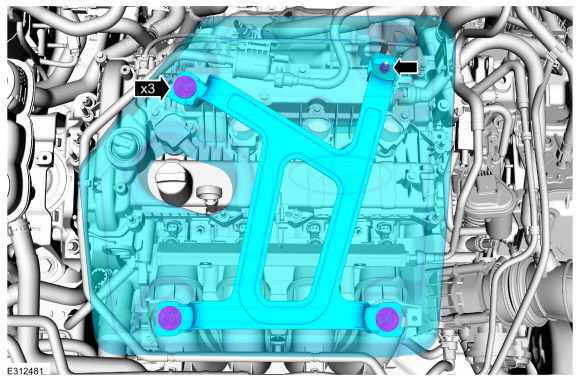
Remove the engine appearance cover nut.
-
Place your hand under the engine appearance cover at
each grommet location and pull straight up to release each grommet from
the studs.
-
After all of the grommets have been released from the studs, remove the appearance cover from the engine.
-
Remove the engine appearance cover nut.
 |
-
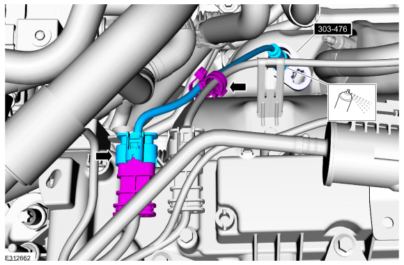
Disconnect the electrical connector and the harness retainer. Remove the HO2S .
Use Special Service Tool: 303-476 (T94P-9472-A) Socket, Exhaust Gas Oxygen Sensor.
Material: Motorcraft® Penetrating and Lock Lubricant / XL-1
 |
Installation
-
To install, reverse the removal procedure.
-
-
Calculate the correct torque wrench setting for the
following torque. Refer to Torque Wrench Adapter Formula in the Apex.
-
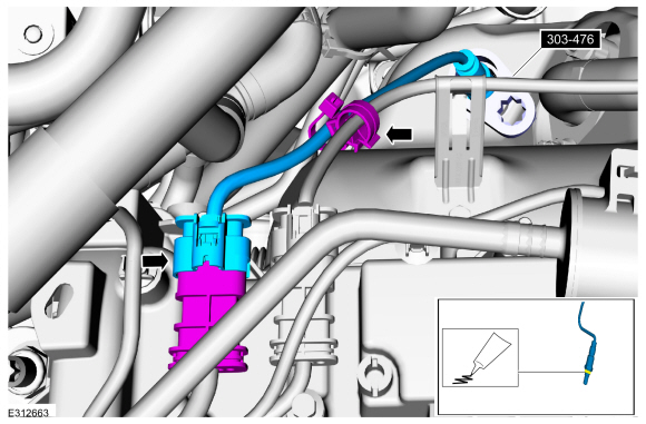
Install the HO2S . Connect the harness retainer and the electrical connector.
Use Special Service Tool: 303-476 (T94P-9472-A) Socket, Exhaust Gas Oxygen Sensor.
Material: Motorcraft® High Temperature Nickel Anti-Seize Lubricant / XL-2
Torque: 35 lb.ft (48 Nm)
-
Calculate the correct torque wrench setting for the
following torque. Refer to Torque Wrench Adapter Formula in the Apex.
 |
-
-
NOTE: Lubricating the grommets with silicone grease will aid in the installation of the engine appearance cover, and any future removal and installation of the cover.
Lubricate each grommet with silicone grease.
Material: Motorcraft® Silicone Brake Caliper Grease and Dielectric Compound / XG-3-A (ESA-M1C200-A) (ESE-M1C171-A)
-
Position the engine appearance cover onto engine with the grommets aligned with the studs.
-
Press down on the engine appearance cover at each grommet location to attach the grommets onto the studs.
-
Install the engine appearance cover nut.
Torque: 44 lb.in (5 Nm)
-
If the engine appearance cover stud bolt is loosened
or removed, it must be installed/tightened into the valve cover.
Torque: 62 lb.in (7 Nm)
-
|
 Removal and Installation - Engine Coolant Temperature (ECT) Sensor
Special Tool(s) /
General Equipment
Locking Pliers
Materials
Name
Specification
Motorcraft® Orange Concentrated Antifreeze/CoolantVC-3-B
WSS-M97B44-D
Removal
NOTE:
Removal steps in this procedure may contain installation details...
 Removal and Installation - Knock Sensor (KS)
Removal
NOTE:
Removal steps in this procedure may contain installation details.
Remove the intake manifold.
Refer to: Intake Manifold (303-01C Engine, Removal and Installation)...
Other information:
Ford Escape 2020-2026 Service Manual: Description and Operation - Climate Control System - Vehicles With: Electronic Manual Temperature Control (EMTC) - System Operation and Component Description
System Operation System Diagram Item Description 1 GWM 2 Ambient Air Temperature (AAT) sensor 3 PCM 4 A/C pressure transducer 5 A/C clutch relay 6 A/C compressor clutch field coil 7 HVAC Control Module 8 Air distribution door actuator 9 Temperature door actuator 10 Air inlet door actuator 11..
Ford Escape 2020-2026 Service Manual: Description and Operation - Transmission Cooling - Hybrid Electric Vehicle (HEV) - Overview
Overview The transmission fluid cooling system consists of the following: Transmission fluid cooler tubes Transmission fluid cooler This vehicle is equipped with an external air cooled transmission fluid cooler. Transmission fluid flows from the transmission through the transmission fluid cooler via the transmission fluid cooler tubes. Component Location Item..
Categories
- Manuals Home
- 4th Generation Ford Escape Owners Manual
- 4th Generation Ford Escape Service Manual
- Plug-In Hybrid Electric Vehicle Drive Modes
- Switching the Lane Keeping System On and Off. Switching the Lane Keeping System Mode. Alert Mode
- General Procedures - Brake Service Mode Activation and Deactivation
- New on site
- Most important about car
Engine Oil
Engine Oil Dipstick Overview

Copyright © 2026 www.fordescape4.com