Ford Escape: Front Drive Halfshafts / Removal and Installation - Front Halfshaft LH
Special Tool(s) / General Equipment
 |
204-161
(T97P-1175-A)
Installer, Halfshaft TKIT-1997-LM2 TKIT-1997-F/FM2 TKIT-1997-FLM2 |
 |
205-D070
(D93P-1175-B)
Remover, Front Wheel Hub |
| Tie Rod End Remover | |
Removal
-
Remove the wheel and tire.
Refer to: Wheel and Tire (204-04A Wheels and Tires, Removal and Installation).
-
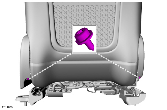
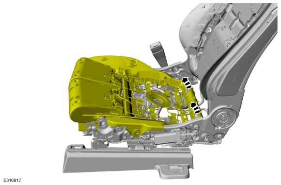
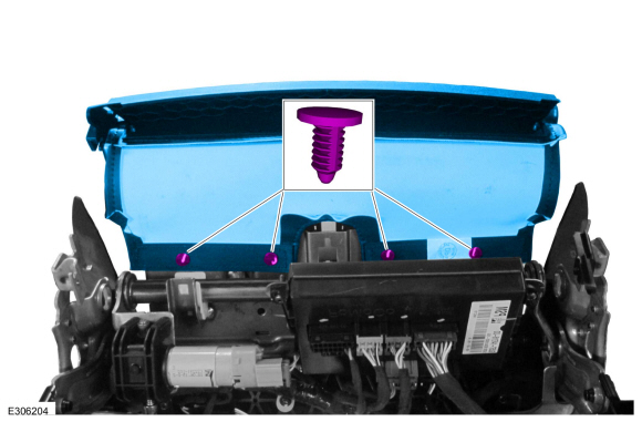
Remove the retainers and the underbody shield.
 |
-
Remove and discard the wheel hub nut.
 |
-
-
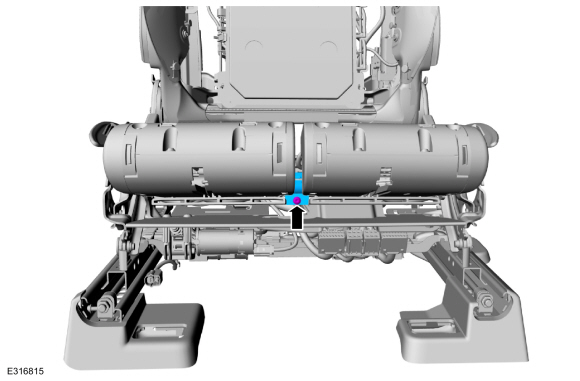
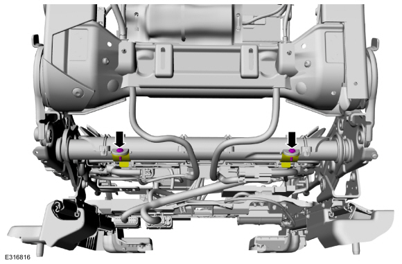
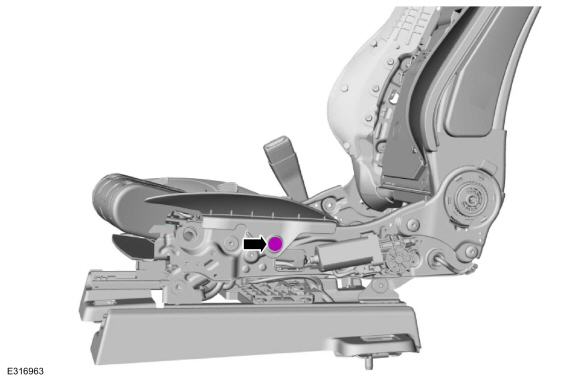
Remove the bolt and position aside the brake hose.
-
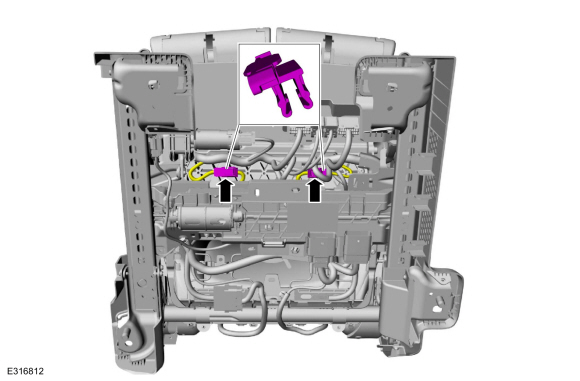
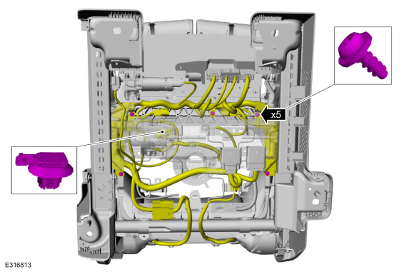
Unclip the 2 wire retainers and position aside the wheel speed sensor wiring harness.
-
Remove the bolt and position aside the brake hose.
 |
-
NOTICE: Do not use a hammer to separate the tie rod end from the wheel knuckle or damage to the wheel knuckle may result.
NOTICE: Use care when installing the tie rod separator or damage to the tie rod end boot may occur.
NOTE: Use the hex-holding feature to prevent turning of the stud while removing the tie rod end nut.
Remove and discard the tie rod end nut and separate the tie rod end from the wheel knuckle. Remove the halfshaft.
Use the General Equipment: Tie Rod End Remover
 |
-
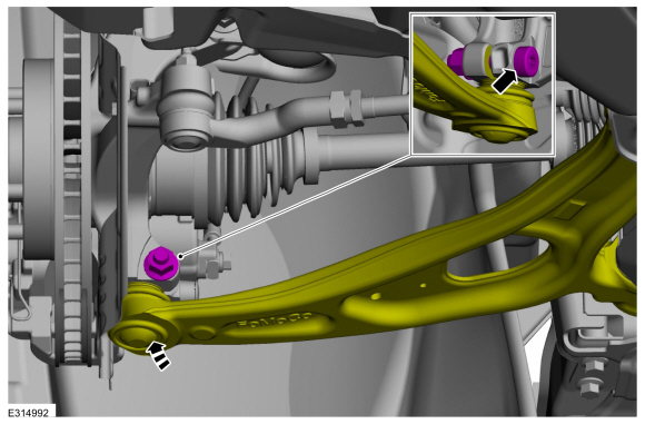
NOTICE: Do not use a prying device to open the slot in the knuckle to separate the lower ball joint from the knuckle assembly. Damage to the knuckle assembly may occur.
NOTICE: Do not use a prying device or separator fork between the ball joint and the wheel knuckle. Damage to the ball joint or ball joint seal may result. Only use the pry bar by inserting it into the lower arm body opening.
NOTICE: Use care when releasing the lower arm and wheel knuckle into the resting position or damage to the ball joint seal may occur.
NOTICE: Do not use power tools to remove or install the lower arm outboard nut. Damage to the ball joint or ball joint seal may occur.
NOTE: Use the TORX PLUS® holding feature to prevent the ball stud from turning while removing or installing the lower arm outboard nut. Torx® and TORX PLUS® is a reg. tm of Acument Intellectual Properties, LLC.
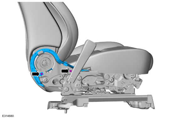
Remove and discard the ball joint pinch bolt and nut and separate the lower arm from the wheel knuckle.
 |
-
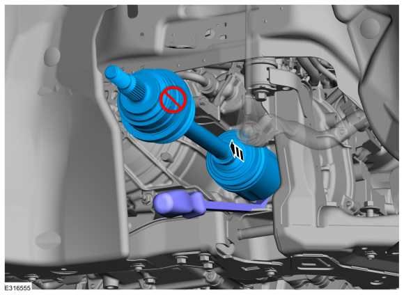
NOTICE: Do not bend the inner joint more than 18 degrees and the outer joint more than 45 degrees. Damage to the shaft will occur.
Using the special tool, press the halfshaft from the wheel bearing and hub. Support the halfshaft in a level position.
Use Special Service Tool: 205-D070 (D93P-1175-B) Remover, Front Wheel Hub.
 |
-
NOTE: Do not pull on the halfshaft. Pull or pry on the inner CV housing only or damage may occur.
Remove the halfshaft.
 |
-
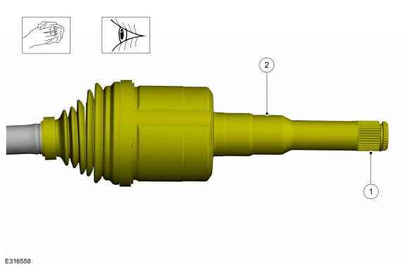
Remove and discard the halfshaft retaining circlip.
 |
Installation
-
Clean and inspect the outer CV housing.
 |
-
Clean and inspect the inner CV housing.
 |
-
NOTE: Make sure new component is installed.
Install the new inner halfshaft retaining circlip.
 |
-
Replace the halfshaft seal.
Refer to: Halfshaft Seal LH (307-01A Automatic Transmission - 8-Speed Automatic Transmission – 8F35/8F40, Removal and Installation).
Refer to: Halfshaft Seal LH (307-01B Automatic Transmission - Automatic Transmission – HF45, Removal and Installation).
Refer to: Halfshaft Seal LH (307-01B Automatic Transmission - Automatic Transmission – HF45, Removal and Installation).
-
NOTE: Insert shaft until circlip is fully seated. When checking if circlip is seated do not pull on CV joints or damage can result.
NOTE: Pull on the inner CV joint to ensure the halfshaft circlip is seated properly.
Insert the halfshaft until the halfshaft retaining clip is fully seated.
 |
-
Pull the halfshaft into the front wheel bearing and wheel hub.
Use Special Service Tool: 204-161 (T97P-1175-A) Installer, Halfshaft.
 |
-
NOTICE: Do not use power tools to remove or install the lower arm outboard nut. Damage to the ball joint or ball joint seal may occur.
NOTE: Use the TORX PLUS® holding feature to prevent the ball stud from turning while removing or installing the lower arm outboard nut. Torx® and TORX PLUS® is a reg. tm of Acument Intellectual Properties, LLC.
Position the ball joint into the wheel knuckle and install the new ball joint pinch bolt and nut.
Torque: 81 lb.ft (110 Nm)
 |
-
NOTICE: Use care when installing the tie rod separator or damage to the tie rod end boot may occur.
NOTE: Use the hex-holding feature to prevent turning of the stud while installing the tie rod end nut.
Attach the tie rod end to the wheel knuckle and install the new tie rod end nut.
Torque: 35 lb.ft (48 Nm)
 |
-
-
Position the brake hose and install the bolt.
Torque: 97 lb.in (11 Nm)
-
Position the wheel speed sensor wiring harness and clip the 2 wire retainers.
-
Position the brake hose and install the bolt.
|
-
NOTICE: Do not tighten the front wheel hub nut with the vehicle on the ground. The nut must be tightened to specification before the vehicle is lowered onto the wheels. Wheel bearing damage will occur if the wheel bearing is loaded with the weight of the vehicle applied.
NOTICE: Install and tighten the new wheel hub nut to specification in a continuous rotation. Always install a new wheel hub nut after loosening or when not tightened to specification in a continuous rotation or damage to the components may occur.
NOTE: Apply the brake to keep the halfshaft from rotating.
While an assistant applies the brake, install the new wheel hub nut.
Torque:
Stage 1: 74 lb.ft (100 Nm)
Stage 2: 60°
 |
-
Check the transmission fluid level.
Refer to: Transmission Fluid Level Check (307-01A Automatic Transmission - 8-Speed Automatic Transmission – 8F35/8F40, General Procedures).
Refer to: Transmission Fluid Level Check (307-01B Automatic Transmission - Automatic Transmission – HF45, General Procedures).
Refer to: Transmission Fluid Level Check (307-01B Automatic Transmission - Automatic Transmission – HF45, General Procedures).
-
Install the underbody shield and tighten the retainers.
Torque: 13 lb.in (1.5 Nm)
|
-
Install the wheel and tire.
Refer to: Wheel and Tire (204-04A Wheels and Tires, Removal and Installation).
 Diagnosis and Testing - Front Drive Halfshafts
Preliminary Inspection
Visually inspect the CV joints, housing, boots, and clamps for obvious signs of mechanical damage.
If an obvious cause for an observed or reported concern is
found, correct the cause (if possible) before proceeding to the next
step
If the cause is not visually evident, verify the symptom and REFER to Symptom Chart: NVH...
 Removal and Installation - Front Halfshaft RH - 1.5L EcoBoost (132kW/180PS) – I3 (Y1)
Special Tool(s) /
General Equipment
204-161
(T97P-1175-A)
Installer, HalfshaftTKIT-1997-LM2TKIT-1997-F/FM2TKIT-1997-FLM2
205-D070
(D93P-1175-B)
Remover, Front Wheel Hub
Tie Rod End Remover
Removal
Remove the wheel and tire...
Other information:
Ford Escape 2020-2026 Service Manual: Description and Operation - Parking Brake - Overview
Overview The parking brake system uses 2 switch activated, Electronic Control Unit (ECU) controlled motors to apply and release the rear brake calipers. The ABS module controls and monitors the parking brake system and sets Diagnostic Trouble Codes (DTCs) when a fault is present in the system...
Ford Escape 2020-2026 Service Manual: Removal and Installation - Subwoofer Speaker
Removal NOTE: Removal steps in this procedure may contain installation details. Remove the RH loadspace trim panel. Refer to: Loadspace Trim Panel (501-05 Interior Trim and Ornamentation, Removal and Installation). Disconnect the electrical connector, separate the wiring guide, remove the bolts and the subwoofer speaker...
Categories
- Manuals Home
- 4th Generation Ford Escape Owners Manual
- 4th Generation Ford Escape Service Manual
- All-Wheel Drive
- Description and Operation - Identification Codes
- Power Outlet - Vehicles With: 12V Power Outlet
- New on site
- Most important about car
Master Access Code
What Is the Master Access Code
The master access code is a factory-set five-digit entry code. You can operate the keypad with the master access code at any time. The master access code is on the owner’s wallet card in the glove box and is available from an authorized dealer.
Displaying the Master Access Code
To display the factory-set code in the information display:
