Ford Escape: Front Suspension / Removal and Installation - Front Stabilizer Bar
Special Tool(s) / General Equipment
| Tie Rod End Remover | |
| Transmission Jack |
Materials
| Name | Specification |
|---|---|
| Motorcraft® Metal Brake Parts Cleaner PM-4-A, PM-4-B, APM-4-C |
- |
Removal
NOTICE: Suspension fasteners are critical parts that affect the performance of vital components and systems. Failure of these fasteners may result in major service expense. Use the same or equivalent parts if replacement is necessary. Do not use a replacement part of lesser quality or substitute design. Tighten fasteners as specified.
NOTE: Removal steps in this procedure may contain installation details.
-
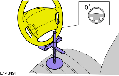
Steering wheel in straight ahead position.
 |
-
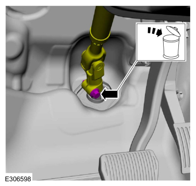
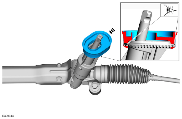
Remove and discard the steering column shaft bolt and disconnect the steering column shaft from the steering gear. WARNING:
Do not reuse steering column shaft bolts. This may
result in fastener failure and steering column shaft detachment or loss
of steering control. Failure to follow this instruction may result in
serious injury to vehicle occupant(s).
WARNING:
Do not reuse steering column shaft bolts. This may
result in fastener failure and steering column shaft detachment or loss
of steering control. Failure to follow this instruction may result in
serious injury to vehicle occupant(s).
Torque: 46 lb.ft (63 Nm)
 |
-
Remove the wheel and tire.
Refer to: Wheel and Tire (204-04A Wheels and Tires, Removal and Installation).
-
Remove the fender splash shield.
Refer to: Fender Splash Shield (501-02 Front End Body Panels, Removal and Installation).
-
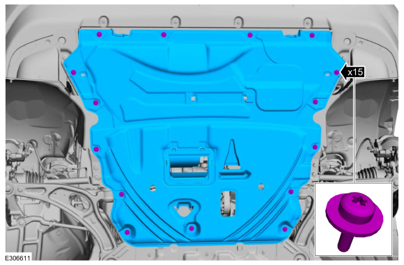
If equipped.
Remove the retainers and the underbody shield.
Torque: 13 lb.in (1.5 Nm)
 |
-
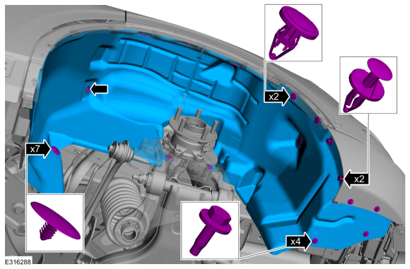
If equipped.
Remove the retainers and the underbody shield.
Torque: 22 lb.in (2.5 Nm)
 |
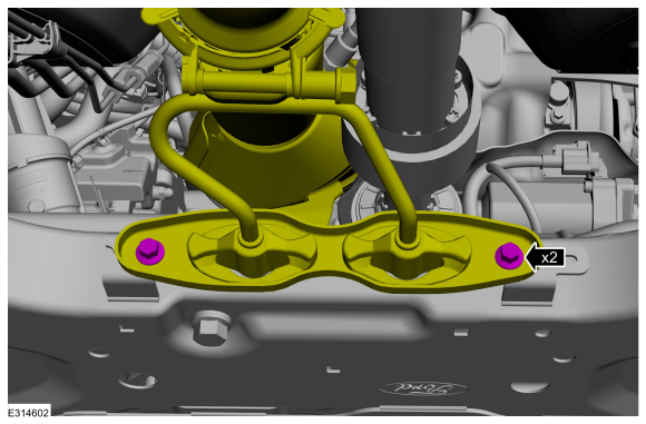
-
If equipped.
Remove the retainers and the underbody shield.
Torque: 22 lb.in (2.5 Nm)
 |
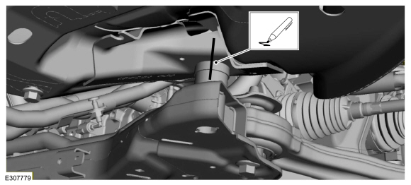
-
If equipped, On both sides.
Remove the bolt and disconnect the ride height sensor from the front lower arm.
Torque: 97 lb.in (11 Nm)
 |
-
Remove front bumper cover.
Refer to: Front Bumper Cover (501-19 Bumpers, Removal and Installation).
-
Remove the subframe support bracket bolts.
Torque: 22 lb.ft (30 Nm)
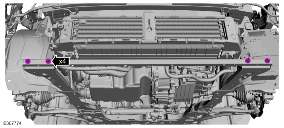 |
-
On both sides.
Remove and discard the bolts and remove the front outer side member.
Torque: 30 lb.ft (40 Nm)
 |
-
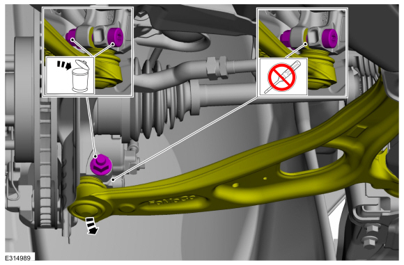
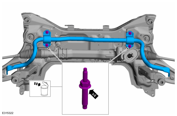
NOTICE: Do not use power tools to remove the stabilizer bar link nut. Damage to the stabilizer bar link ball joint or boot may occur.
NOTE: The stabilizer bar links are designed with low friction ball joints that have a low breakaway torque.
NOTE: Use the TORX PLUS® holding feature to prevent the ball stud from turning while removing or installing the lower arm outboard nut. Torx® and TORX PLUS® is a reg. tm of Acument Intellectual Properties, LLC.
On both sides.
Remove and discard the from stabilizer bar link lower nuts and position aside the front stabilizer bar links.
Torque: 85 lb.ft (115 Nm)
 |
-
NOTICE: Do not use a hammer to separate the outer tie-rod end from the wheel knuckle or damage to the wheel knuckle may result.
NOTICE: Use care when installing the tie rod separator or damage to the outer tie-rod end boot may occur.
NOTE: Use the hex-holding feature to prevent turning of the stud while removing the tie rod end nut.
On both sides.
Remove and discard the tie rod end nut and separate the tie rod end from the wheel knuckle.
Use the General Equipment: Tie Rod End Remover
Torque: 35 lb.ft (48 Nm)
 |
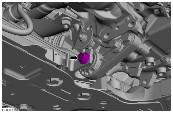
-
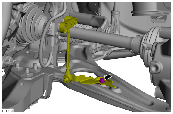
NOTICE: Do not use a prying device to open the slot in the knuckle to separate the lower ball joint from the knuckle assembly. Damage to the knuckle assembly may occur.
NOTICE: Do not use a prying device or separator fork between the ball joint and the wheel knuckle. Damage to the ball joint or ball joint seal may result. Only use the pry bar by inserting it into the lower arm body opening.
NOTICE: Use care when releasing the lower arm and wheel knuckle into the resting position or damage to the ball joint seal may occur.
NOTICE: Do not use power tools to remove or install the lower arm outboard nut. Damage to the ball joint or ball joint seal may occur.
NOTE: Use the TORX PLUS® holding feature to prevent the ball stud from turning while removing or installing the lower arm outboard nut. Torx® and TORX PLUS® is a reg. tm of Acument Intellectual Properties, LLC.
On both sides.
Remove and discard the ball joint pinch bolt and nut and separate the lower arm from the wheel knuckle.
Torque: 66 lb.ft (90 Nm)
 |
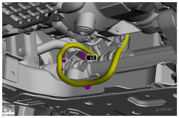
-
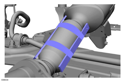
NOTICE: Do not excessively bend or twist the exhaust flexible pipe. Failure to follow these instructions may cause damage to the exhaust flexible pipe.
Support the exhaust flexible pipe.
 |
-
Remove the bolts and position aside the exhaust pipe hanger assembly.
Torque: 18 lb.ft (25 Nm)
 |
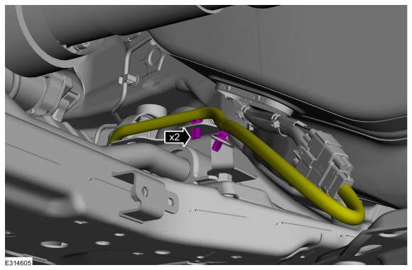
-
Remove the engine roll restrictor bolt.
Torque: 129 lb.ft (175 Nm)
 |
-
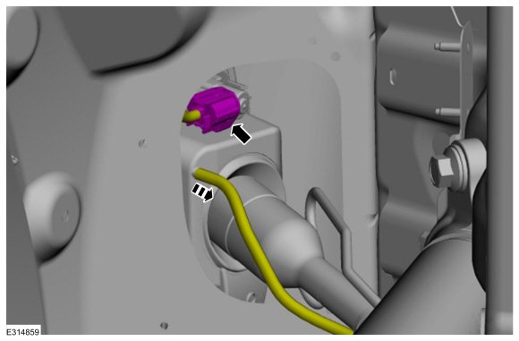
Detach the retainers and position aside the EPAS wiring harness.
 |
-
Unclip the wire harness retainers.
 |
-
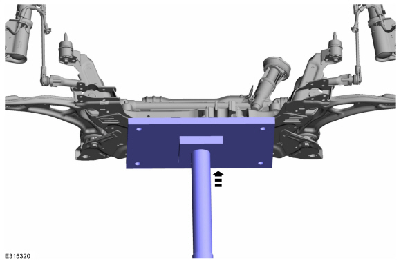
Support the front subframe assembly.
Use the General Equipment: Transmission Jack
 |
-
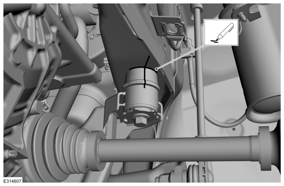
NOTE: Index mark the subframe positioning for reference during the installation procedure.
NOTE: Rear mounting location shown.
On both sides
Index-mark the subframe to the body.
 |
-
NOTE: Index mark the subframe positioning for reference during the installation procedure.
NOTE: Front mounting location shown.
On both sides
Index-mark the subframe to the body.
 |
-
-
Remove and discard the rearward subframe bolts.
Torque:
Stage 1: 159 lb.ft (215 Nm)
Stage 2: 120°
-
Remove the bolts and the subframe brackets.
Torque: 46 lb.ft (63 Nm)
-
Remove and discard the rearward subframe bolts.
 |
-
-
Remove the forward subframe bolts.
Torque: 85 lb.ft (115 Nm)
-
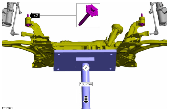
Lower the front subframe assembly from the vehicle.
Dimension: 4 in ( 100 mm)
-
Remove the forward subframe bolts.
 |
-
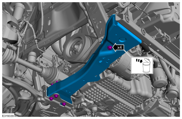
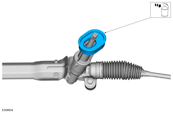
NOTICE: The steering column floor seal is a one time use seal and must be replaced anytime that the front subframe is lowered or separated from the vehicle.
NOTE: Note the position of the component before removal.
Remove and discard the steering column floor seal.
 |
-
Remove and discard the stabilizer bar bracket bolts and remove the stabilizer bar.
Torque: 46 lb.ft (63 Nm)
 |
Installation
-
To install, reverse the removal procedure.
-
NOTE: The steering column floor seal mounting surface must be cleaned using solvent before reinstallation.
Clean and inspect the steering column floor seal mounting surface before reinstallation.
Material: Motorcraft® Metal Brake Parts Cleaner / PM-4-A, PM-4-B, APM-4-C
 |
-
NOTE: Make sure that the floor seal lip is fully wrapped around the carrier on the steering gear.
Install the new steering column floor seal.
 |
-
Check and if necessary adjust the front toe.
Refer to: Front Toe Adjustment (204-00 Suspension System - General Information, General Procedures).
 Description and Operation - Front Suspension - Overview
Overview
The front suspension consists of the following components:
Lower arms
Stabilizer bar, bushings and links
Wheel bearings and wheel hubs
Wheel knuckles
Wheel studs
Front strut and spring assemblies
The
front suspension uses a MacPherson strut system...
 Removal and Installation - Front Stabilizer Bar Link
Removal
NOTICE:
Suspension fasteners are critical parts that affect the
performance of vital components and systems. Failure of these fasteners
may result in major service expense...
Other information:
Ford Escape 2020-2026 Service Manual: Removal and Installation - Instrument Panel Cluster (IPC) Lens
Removal Remove the IPC . Refer to: Instrument Panel Cluster (IPC) (413-01 Instrumentation, Message Center and Warning Chimes, Removal and Installation). Remove the screws. Release the clips and remove the IPC lens...
Ford Escape 2020-2026 Owners Manual: Bluetooth Stereo or USB
Bluetooth Stereo and USB allow you to access media that you store on your Bluetooth device or USB device such as music, audio books or podcasts. The following buttons are available for Bluetooth and USB: You can use the forward, reverse, pause or play buttons to control the audio playback...
Categories
- Manuals Home
- 4th Generation Ford Escape Owners Manual
- 4th Generation Ford Escape Service Manual
- Switching the Lane Keeping System On and Off. Switching the Lane Keeping System Mode. Alert Mode
- Switching the Rear Window Wiper On and Off. Reverse Wipe
- Adjusting the Headlamps
- New on site
- Most important about car
Adjusting the Seatbelts During Pregnancy
WARNING: Always ride and drive with your seatback upright and properly fasten your seatbelt. Fit the lap portion of the seatbelt snugly and low across the hips. Position the shoulder portion of the seatbelt across your chest. Pregnant women must follow this practice. See the following figure.
