Ford Escape 2020-2026 Service Manual / Body and Paint / Body and Paint / Body Closures / Removal and Installation - Fuel Filler Door Assembly
Ford Escape: Body Closures / Removal and Installation - Fuel Filler Door Assembly
Special Tool(s) / General Equipment
| Flat Headed Screw Driver | |
| Knife |
Removal
NOTE: Removal steps in this procedure may contain installation details.
NOTE: The fuel filler door assembly is damaged during the removal process and requires a new fuel filler door assembly installed.
-
Disconnect the battery.
Refer to: Battery Disconnect and Connect (414-01) .
-
With the vehicle in NEUTRAL, position it on a hoist.
Refer to: Jacking and Lifting (100-02) .
-
3.Remove the LHR wheel and tire.
Refer to: Wheel and Tire (204-04A Wheels and Tires, Removal and Installation).
-
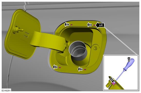
Remove the retainers and screws
Torque: 17 lb.in (1.9 Nm)
.jpg) |
-
Remove the retainers.
.jpg) |
-
Remove the fuel filler door.
Refer to: Fuel Filler Door (501-03 Body Closures, Removal and Installation).
-
-
Disconnect the electrical connector.
-
disconnect the vent hose.
-
Disconnect the electrical connector.
.jpg) |
-
Using a knife, slice the holes in the indicated areas.
Use the General Equipment: Knife
.jpg) |
-
Insert the screwdriver and release the clips while pulling the fuel filler door housing away from the vehicle
Use the General Equipment: Flat Headed Screw Driver
.jpg) |
-
Pull the fuel filler door housing away from the vehicle
 |
Installation
-
To install, reverse the removal procedure.
-
NOTICE: Make sure that the fuel information labels are installed at the noted removal position.
NOTE: This step is only necessary if the component needs to be replaced.
Install the fuel labels on the fuel filler door hinge arm and rear panel.
 Removal and Installation - Fuel Filler Door
Special Tool(s) /
General Equipment
Flat Headed Screw Driver
Removal
Open the fuel filler door.
Release the retaining tab and slide the fuel filler door from the fuel filler door hinge...
 Removal and Installation - Hands-Free Liftgate Actuation Lower Sensor
Removal
With the vehicle in NEUTRAL, position it on a hoist.
Refer to: Jacking and Lifting (100-02)
.
Disconnect the hands-free liftgate actuation lower sensor electrical connector...
Other information:
Ford Escape 2020-2026 Owners Manual: Electric Vehicle Information (If Equipped)
Power Flow The Power Flow information for your plug-in hybrid vehicle is available through the Home screen or under Apps. Vehicle Operational States Power will flow to or from the front and rear wheels depending on operational state and drive conditions...
Ford Escape 2020-2026 Service Manual: Removal and Installation - Rear Door Trim Panel
Special Tool(s) / General Equipment Pick Hook Interior Trim Remover Removal NOTE: LH (left hand) shown, RH (right hand) similar. NOTE: Removal steps in this procedure may contain installation details. NOTICE: The door latch must be in the locked position prior to disassembly or the door lock feature may not function correctly after installation...
Categories
- Manuals Home
- 4th Generation Ford Escape Owners Manual
- 4th Generation Ford Escape Service Manual
- Opening and Closing the Hood
- Plug-In Hybrid Electric Vehicle Drive Modes
- Drive Modes
- New on site
- Most important about car
Adjusting the Seatbelts During Pregnancy
WARNING: Always ride and drive with your seatback upright and properly fasten your seatbelt. Fit the lap portion of the seatbelt snugly and low across the hips. Position the shoulder portion of the seatbelt across your chest. Pregnant women must follow this practice. See the following figure.

Copyright © 2026 www.fordescape4.com