Ford Escape: Anti-Lock Brake System (ABS) and Stability Control / Removal and Installation - Hydraulic Control Unit (HCU) - Vehicles With: Vacuum Brake Booster
Removal
NOTE: Removal steps in this procedure may contain installation details.
NOTE: A new HCU is equipped with an ABS module. A new ABS module does not come equipped with an HCU .
-
NOTE: The PMI process must begin with the current ABS module installed. If the current ABS module does not respond to the diagnostic scan tool, the tool may prompt for As-Built Data as part of the repair.
Using a diagnostic scan tool, begin the PMI process for the ABS module following the onscreen instructions.
-
Remove the air cleaner outlet pipe.
-
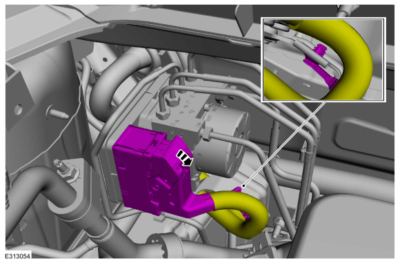
Disconnect the ABS module electrical connector and detch the pin-type retainer.
 |
-
NOTICE: Make sure that all openings are sealed.
NOTICE: If the fluid is spilled on the paintwork, the affected area must be immediately washed down with cold water.
Disconnect the brake tube fittings and detch the pin-type retainer.
Torque: 159 lb.in (18 Nm)
 |
-
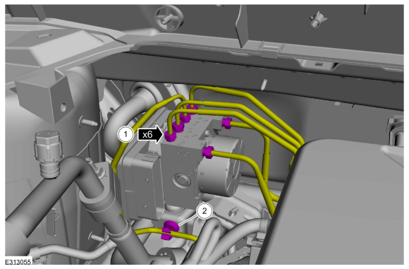
Remove the nut, bolt, and the HCU .
Torque: 18 lb.ft (25 Nm)
 |
-
NOTE: The following step is only necessary when installing a new HCU and ABS module assembly.
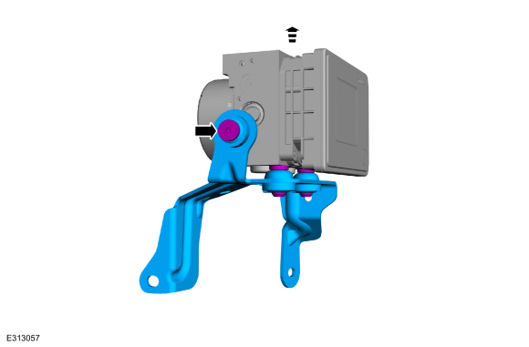
Remove the bolt and the HCU bracket.
Torque: 80 lb.in (9 Nm)
 |
Installation
-
To install, reverse the removal procedure.
-
Using a diagnostic scan tool, complete the PMI process for the ABS module following the on-screen instructions.
-
Bleed the brake system.
Refer to: Brake System Pressure Bleeding - Vehicles With: Vacuum Brake Booster (206-00 Brake System - General Information, General Procedures).
-
Carry out the following service functions using the scan
tool and following the diagnostic scan tool on-screen instructions.
-
Carry out the ABS Calibration.
-
Carry out the HCU Coil Solenoid Calibration.
-
Run the PCM
PATS
programming application and then carry out the Module Initialization
(Parameter Reset) using the scan tool and following the diagnostic scan
tool on-screen instructions.
-
Carry out the ABS Calibration.
 Removal and Installation - Front Wheel Speed Sensor
Materials
Name
Specification
Motorcraft® Metal Brake Parts CleanerPM-4-A, PM-4-B, APM-4-C
-
Removal
NOTE:
Removal steps in this procedure may contain installation details...
 Removal and Installation - Rear Wheel Speed Sensor - AWD
Materials
Name
Specification
Motorcraft® Metal Brake Parts CleanerPM-4-A, PM-4-B, APM-4-C
-
Removal
NOTE:
Removal steps in this procedure may contain installation details...
Other information:
Ford Escape 2020-2025 Service Manual: Removal and Installation - Fuel Vapor Vent Valve - Hybrid Electric Vehicle (HEV)
Removal WARNING: Do not smoke, carry lighted tobacco or have an open flame of any type when working on or near any fuel-related component. Highly flammable mixtures may be present and may be ignited. Failure to follow these instructions may result in serious personal injury...
Ford Escape 2020-2025 Service Manual: Description and Operation - Charging System - 1.5L EcoBoost (132kW/180PS) – I3 (Y1) - Overview
Overview The generator is driven by the FEAD belt. When the engine is started, the generator begins to generate AC voltage which is internally converted to DC voltage. The DC voltage is controlled by the voltage regulator and supplied to the battery...
Categories
- Manuals Home
- 4th Generation Ford Escape Owners Manual
- 4th Generation Ford Escape Service Manual
- General Procedures - Brake Service Mode Activation and Deactivation
- Traction Control
- General Procedures - Transmission Fluid Level Check
- New on site
- Most important about car
Master Access Code
What Is the Master Access Code
The master access code is a factory-set five-digit entry code. You can operate the keypad with the master access code at any time. The master access code is on the owner’s wallet card in the glove box and is available from an authorized dealer.
Displaying the Master Access Code
To display the factory-set code in the information display:
