Ford Escape 2020-2026 Service Manual / Chassis / Driveline / Driveshaft / Removal and Installation - Rear Driveshaft
Ford Escape: Driveshaft / Removal and Installation - Rear Driveshaft
Special Tool(s) / General Equipment
| Flat Headed Screw Driver | |
| Punch | |
| Copper Hammer |
Removal
-
Remove the muffler and tailpipe.
Refer to: Muffler and Tailpipe (309-00A Exhaust System - 1.5L EcoBoost (132kW/180PS) – I3 (Y1), Removal and Installation).
Refer to: Muffler and Tailpipe (309-00B Exhaust System - 2.0L EcoBoost (177kW/240PS) – MI4, Removal and Installation).
Refer to: Muffler and Tailpipe (309-00 Exhaust System) .
-
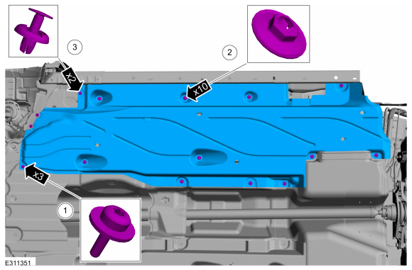
Remove the LH front air deflector.
-
Remove the screws and washers.
-
Remove the stamped nuts.
-
Remove the push pins.
-
Remove the screws and washers.
 |
-
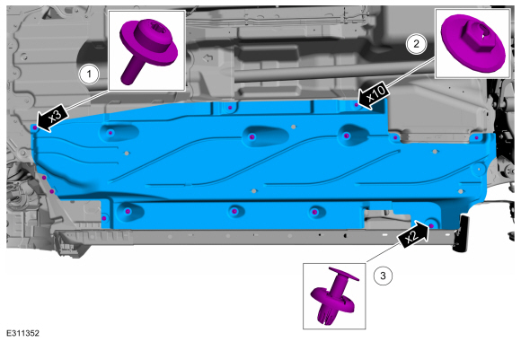
Remove the RH front air deflector.
-
Remove the screws and washers.
-
Remove the stamped nuts.
-
Remove the push pins.
-
Remove the screws and washers.
 |
-
Remove the heat shield.
-
Remove the screws and washers.
-
Remove the push pin.
-
Remove the screws and washers.
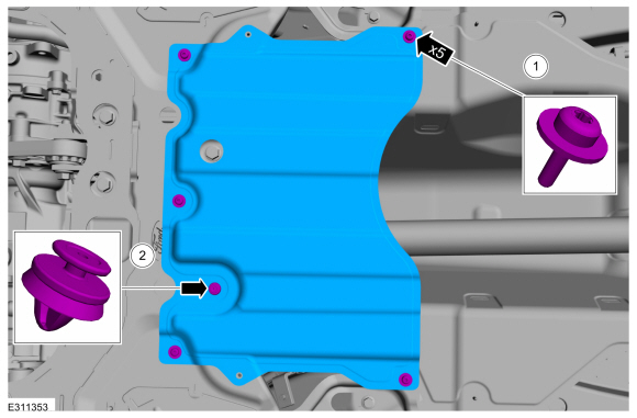 |
-
Remove the stamped nuts and the heat shield.
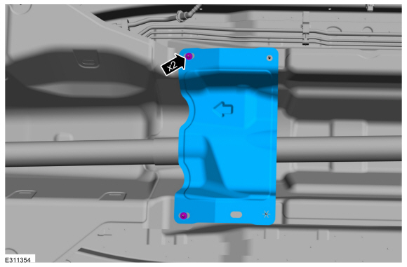 |
-
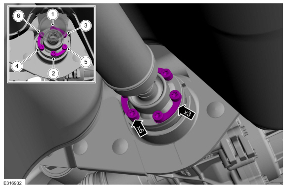
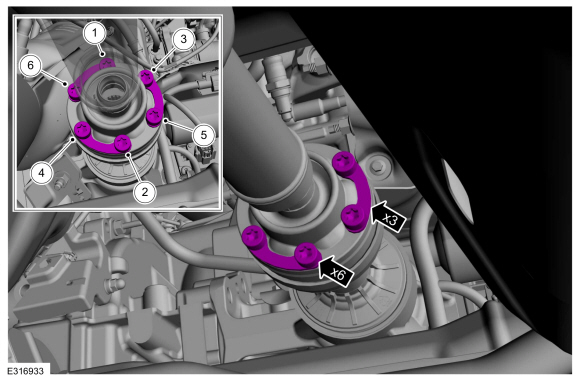
NOTE: The installation step requires the aid of another technician.
Remove and discard the driveshaft to PTU bolts and the retaining straps.
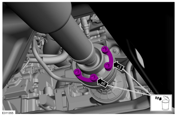 |
-
Separate the driveshaft from the PTU flange.
-
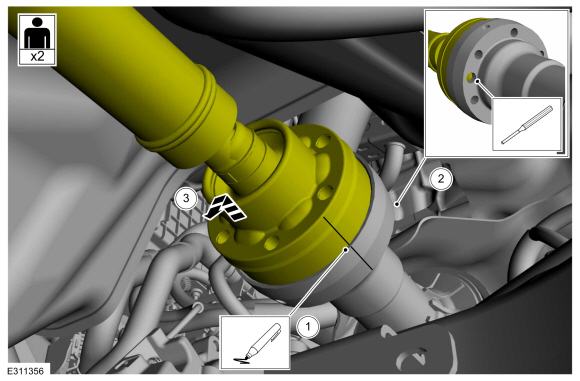
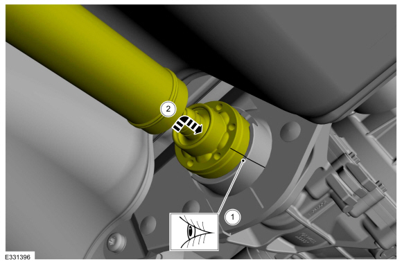
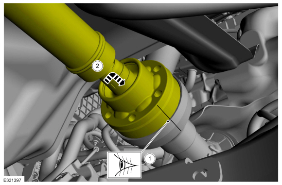
NOTE: Make sure that the component aligns with the installation mark.
Index-mark the driveshaft and PTU flange.
-
NOTICE: Do not remove driveshaft from the PTU flange by pulling on the driveshaft tube. Damage to the CV-joint can result.
NOTE: This is a tight fit, do not remove the CV flange from the PTU flange at this time.
Using general equipments, separate the driveshaft from the PTU flange.
Use the General Equipment: Punch
Use the General Equipment: Copper Hammer
-
NOTE: This step requires the aid of another technician.
Remove the driveshaft from the PTU flange.
-
 |
-
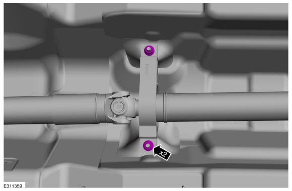
Remove and discard the driveshaft to RDU flange bolts and retaining straps.
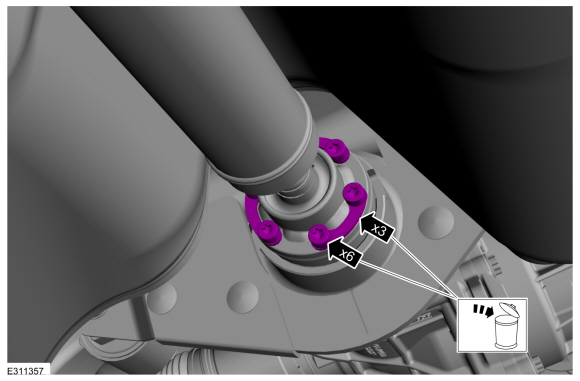 |
-
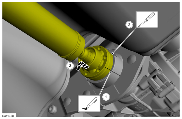
Separate the driveshaft from the drive pinion flange.
-
NOTE: Make sure that the component aligns with the installation mark.
Index-mark the driveshaft and RDU flange.
-
Using general equipment, separate the driveshaft from drive pinion flange.
Use the General Equipment: Flat Headed Screw Driver
-
Remove the driveshaft from the RDU flange.
-
 |
-
Remove the center bearing nuts.
 |
-
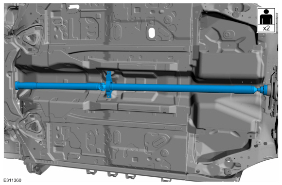
NOTE: Do not allow the angle of the driveshaft U-joint exceed 5 degrees.
NOTE: This step requires the aid of another technician.
With the help of an assistant, remove the driveshaft.
 |
Installation
-
NOTE: This step requires the aid of another technician.
With the help of an assistant, install the driveshaft.
|
-
Install the center bearing nuts.
Torque: 41 lb.ft (55 Nm)
|
-
-
Align the index-mark on the driveshaft and RDU flange.
-
Fit the driveshaft into the RDU flange.
-
Align the index-mark on the driveshaft and RDU flange.
 |
-
-
Install the new driveshaft to the RDU flange retaining straps and bolts.
-
Tighten the driveshaft to the RDU flange bolts in criss-cross pattern.
Torque: 26 lb.ft (35 Nm)
-
Install the new driveshaft to the RDU flange retaining straps and bolts.
 |
-
-
Align the index-mark on the driveshaft and PTU flange.
-
Fit the driveshaft into the drive pinion flange.
-
Align the index-mark on the driveshaft and PTU flange.
 |
-
-
Install the new driveshaft to the PTU flange retaining straps and bolts.
-
Tighten the driveshaft to the PTU flange bolts in criss-cross pattern.
Torque: 26 lb.ft (35 Nm)
-
Install the new driveshaft to the PTU flange retaining straps and bolts.
 |
-
Install the heat shield and the stamped nuts.
|
-
Install the heat shield.
-
Install the screws and washers.
-
Install the push pin.
-
Install the screws and washers.
|
-
Install the RH front air deflector.
-
Install the screws and washers.
-
Install the stamped nuts.
-
Install the push pins.
-
Install the screws and washers.
|
-
Install the LH front air deflector.
-
Install the screws and washers.
-
Install the stamped nuts.
-
Install the push pins.
-
Install the screws and washers.
|
-
Install the muffler and tailpipe.
Refer to: Muffler and Tailpipe (309-00A Exhaust System - 1.5L EcoBoost (132kW/180PS) – I3 (Y1), Removal and Installation).
Refer to: Muffler and Tailpipe (309-00B Exhaust System - 2.0L EcoBoost (177kW/240PS) – MI4, Removal and Installation).
Refer to: Muffler and Tailpipe (309-00 Exhaust System) .
 General Procedures - Driveshaft Runout and Balancing
Special Tool(s) /
General Equipment
100-002
(TOOL-4201-C)
Holding Fixture with Dial Indicator Gauge
Inspection
NOTE:
Driveline vibration exhibits a higher frequency and lower
amplitude then high-speed shake...

Other information:
Ford Escape 2020-2026 Owners Manual: Steering
Electric Power Steering Electric Power Steering Precautions WARNING: The electric power steering system has diagnostic checks that continuously monitor the system. If a fault is detected, a message displays in the information display. Stop your vehicle as soon as it is safe to do so. Switch the vehicle off. After at least 10 seconds, switch the vehicle on and watch the information display ..
Ford Escape 2020-2026 Service Manual: Diagnosis and Testing - Seatbelt Systems
Symptom Chart(s) Preliminary Inspection Diagnostics in this manual assume a certain skill level and knowledge of Ford-specific diagnostic practices. REFER to: Diagnostic Methods (100-00 General Information, Description and Operation). Before diagnosing or repairing the seatbelt system, inspect the following items: Seatbelt webbing integrity (torn, frayed, cut or stretched) Seatb..
Categories
- Manuals Home
- 4th Generation Ford Escape Owners Manual
- 4th Generation Ford Escape Service Manual
- Power Outlet - Vehicles With: 12V Power Outlet
- Switching the Rear Window Wiper On and Off. Reverse Wipe
- Symbols Glossary
- New on site
- Most important about car
Fastening the Seatbelts

Copyright © 2026 www.fordescape4.com