Ford Escape: Roof Sheet Metal Repairs / Removal and Installation - Roof Panel
Special Tool(s) /
General Equipment
| Resistance Spotwelding Equipment |
| Knife |
| 8 mm Drill Bit |
| MIG/MAG Welding Equipment |
| Spot Weld Drill Bit |
| Locking Pliers |
Materials
| Name |
Specification |
Metal Bonding Adhesive
TA-1, TA-1-B, 3M™ 08115, LORD Fusor® 108B, Henkel Teroson EP 5055 |
-
|
Seam Sealer
TA-2-B, 3M™ 08308, LORD Fusor® 803DTM |
-
|
Removal
 WARNING:
Electric vehicles damaged by a crash may have compromised
high voltage safety systems and present a potential high voltage
electrical shock hazard. Exercise caution and wear appropriate Personal
Protective Equipment (PPE) safety gear, including high voltage safety
gloves and boots. Remove all metallic jewelry, including watches and
rings. Isolate the HV system as directed by the Ford Emergency Response
Guide for the vehicle. Failure to follow these instructions may result
in serious personal injury or death.
WARNING:
Electric vehicles damaged by a crash may have compromised
high voltage safety systems and present a potential high voltage
electrical shock hazard. Exercise caution and wear appropriate Personal
Protective Equipment (PPE) safety gear, including high voltage safety
gloves and boots. Remove all metallic jewelry, including watches and
rings. Isolate the HV system as directed by the Ford Emergency Response
Guide for the vehicle. Failure to follow these instructions may result
in serious personal injury or death.
NOTICE:
Battery electric vehicle (BEV), hybrid electric vehicle
(HEV) and plug-in hybrid electric vehicle (PHEV) contain a high-voltage
battery. Before cutting or welding near the high-voltage battery it must
be removed to avoid damage.
NOTICE:
The high-voltage battery in a battery electric vehicle
(BEV), hybrid electric vehicle (HEV) or plug-in hybrid electric vehicle
(PHEV) can be affected and damaged by excessively high temperatures. The
temperature in some body shop paint booths can exceed 60° C (140° F).
Therefore, during refinishing operations, the paint booth temperature
must set at or below 60° C (140° F) with a bake time of 45 minutes or
less. Temperatures in excess of 60° C (140° F) or bake durations longer
than 45 minutes will require the high-voltage battery be removed from
the vehicle prior to placing in the paint booth.
NOTICE:
If refinishing cure temperatures exceed 60° C (140° F), the
charge port light ring on plug-in vehicles must be removed.
NOTE:
Factory welds may be substituted with resistance or metal
inert gas (MIG) plug welds. Resistance welds may not be placed directly
over original location. They must be placed adjacent to original
location and match factory welds in quantity. Metal inert gas (MIG) plug
welds must equal factory welds in both location and quantity.
NOTE:
Left hand (LH) side shown, right hand (RH) side similar.
-
WARNING:
Before beginning any service procedure in this
manual, refer to health and safety warnings in section 100-00 General
Information. Failure to follow this instruction may result in serious
personal injury.
Refer to: Health and Safety Precautions (100-00 General Information, Description and Operation).
Refer to: High Voltage System Health and Safety Precautions - Overview (100-00 General Information, Description and Operation).
-
Depower the SRS .
Refer to: Supplemental Restraint System (SRS) Depowering (501-20B Supplemental Restraint System, General Procedures).
-
Remove the lift gate.
Refer to: Liftgate (501-03 Body Closures, Removal and Installation).
-
Remove the lift gate opening weather strip.
-
On Both Sides:
Remove the side curtain air bag.
Refer to: Side Curtain Airbag (501-20B Supplemental Restraint System, Removal and Installation).
-
Remove the rear header cover.
-
If Equipped:
Remove the roof rack.
Refer to: Roof Rail (501-08 Exterior Trim and Ornamentation, Removal and Installation).
-
On Both Sides:
Remove the roof ditch mouldings.
Refer to: Roof Moulding (501-08 Exterior Trim and Ornamentation, Removal and Installation).
-
On Both Sides:
Remove the lift gate hinges.
-
Remove the satellite antenna.
Refer to: Satellite Radio / Global Positioning System (GPS) Antenna
(415-00 Information and Entertainment System - General Information,
Removal and Installation).
-
Remove the windshield.
Refer to: Fixed Glass (501-11 Glass, Frames and Mechanisms, General Procedures).
-
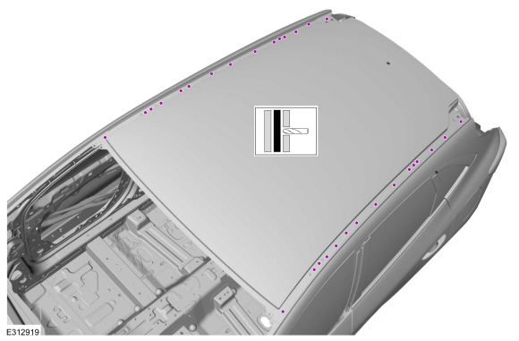
Remove the welds.
Use the General Equipment: Spot Weld Drill Bit
-
Remove the welds.
Use the General Equipment: Spot Weld Drill Bit
-
Remove the welds.
Use the General Equipment: Spot Weld Drill Bit
-
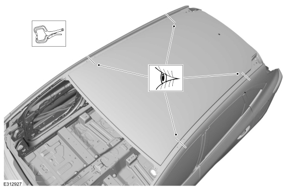
NOTE:
Leave as much noise vibration and harshness (NVH) foam intact on the roof bows as possible.
Cut the NVH material between the roof panel and roof bows.
Use the General Equipment: Knife
-
With the help of an assistant, remove the roof panel.
Installation
WARNING:
Electric vehicles damaged by a crash may have compromised
high voltage safety systems and present a potential high voltage
electrical shock hazard. Exercise caution and wear appropriate Personal
Protective Equipment (PPE) safety gear, including high voltage safety
gloves and boots. Remove all metallic jewelry, including watches and
rings. Isolate the HV system as directed by the Ford Emergency Response
Guide for the vehicle. Failure to follow these instructions may result
in serious personal injury or death.
NOTICE:
Battery electric vehicle (BEV), hybrid electric vehicle
(HEV) and plug-in hybrid electric vehicle (PHEV) contain a high-voltage
battery. Before cutting or welding near the high-voltage battery it must
be removed to avoid damage.
NOTICE:
The high-voltage battery in a battery electric vehicle
(BEV), hybrid electric vehicle (HEV) or plug-in hybrid electric vehicle
(PHEV) can be affected and damaged by excessively high temperatures. The
temperature in some body shop paint booths can exceed 60° C (140° F).
Therefore, during refinishing operations, the paint booth temperature
must set at or below 60° C (140° F) with a bake time of 45 minutes or
less. Temperatures in excess of 60° C (140° F) or bake durations longer
than 45 minutes will require the high-voltage battery be removed from
the vehicle prior to placing in the paint booth.
NOTICE:
If refinishing cure temperatures exceed 60° C (140° F), the
charge port light ring on plug-in vehicles must be removed.
NOTE:
Factory welds may be substituted with resistance or metal
inert gas (MIG) plug welds. Resistance welds may not be placed directly
over original location. They must be placed adjacent to original
location and match factory welds in quantity. Metal inert gas (MIG) plug
welds must equal factory welds in both location and quantity.
NOTE:
Left hand (LH) side shown, right hand (RH) side similar.
-
WARNING:
Before beginning any service procedure in this
manual, refer to health and safety warnings in section 100-00 General
Information. Failure to follow this instruction may result in serious
personal injury.
Refer to: Health and Safety Precautions (100-00 General Information, Description and Operation).
Refer to: High Voltage System Health and Safety Precautions - Overview (100-00 General Information, Description and Operation).
-
Health and safety precautions.
Refer to: Health and Safety Precautions (100-00 General Information, Description and Operation).
-
Sand to remove old adhesive, sealer and clean.
-
Drill for plug weld holes.
Use the General Equipment: 8 mm Drill Bit
-
Install locally obtained NVH patches.
-
With the help of an assistant, install the roof panel.
-
Correctly position and index mark the roof panel.
-
With the help of an assistant, remove the roof panel.
-
Apply adhesive.
Material: Metal Bonding Adhesive
/ TA-1, TA-1-B, 3M™ 08115, LORD Fusor® 108B, Henkel Teroson EP 5055
-
With the help of an assistant, install the roof panel.
-
NOTE:
Do not lift the panel from the body once installed.
If the panel requires re-positioning, slide the panel to the correct
location.
NOTE:
Assure full adhesive contact at all locations, apply additional adhesive as required.
NOTE:
Do not remove excess adhesive squeeze out. Smooth into roof ditch area to act as a sealer.
Properly position and clamp the roof panel.
Use the General Equipment: Locking Pliers
-
Install the welds.
Use the General Equipment: Resistance Spotwelding Equipment
-
Install the welds.
Use the General Equipment: Resistance Spotwelding Equipment
-
Install the welds.
Use the General Equipment: MIG/MAG Welding Equipment
-
Metal finish all welds as necessary using typical metal finishing techniques and materials.
-
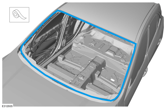
Seam Sealing:
All seams must be sealed to production level.
Material: Seam Sealer
/ TA-2-B, 3M™ 08308, LORD Fusor® 803DTM
-
Sand to remove e-coat, old adhesive and clean.
-
Apply a Ford approved, epoxy-based primer and allow to dry.
-
Mask off the area.
-
Refinish the entire repair using a Ford approved paint system and typical refinishing techniques.
-
Unmask the area.
-
Install the windshield.
Refer to: Fixed Glass (501-11 Glass, Frames and Mechanisms, General Procedures).
-
Install the satellite antenna.
Refer to: Satellite Radio / Global Positioning System (GPS) Antenna
(415-00 Information and Entertainment System - General Information,
Removal and Installation).
-
Install the lift gate hinges.
Torque:
22 lb.ft (30 Nm)
-
On Both Sides:
Install the roof ditch moulding.
Refer to: Roof Moulding (501-08 Exterior Trim and Ornamentation, Removal and Installation).
-
On Both Sides:
Install the side curtain air bag.
Refer to: Side Curtain Airbag (501-20B Supplemental Restraint System, Removal and Installation).
-
If Equipped:
Install the roof rack.
Refer to: Roof Rail (501-08 Exterior Trim and Ornamentation, Removal and Installation).
-
Install the lift gate.
Refer to: Liftgate (501-03 Body Closures, Removal and Installation).
-
Install the lift gate weather strip.
-
Align the lift gate.
Refer to: Liftgate Alignment (501-03 Body Closures, General Procedures).
-
Install the rear header cover.
-
Repower the SRS .
Refer to: Supplemental Restraint System (SRS) Repowering (501-20B Supplemental Restraint System, General Procedures).
Special Tool(s) /
General Equipment
MIG/MAG Welding Equipment
Spot Weld Drill Bit
Locking Pliers
Removal
WARNING:
Electric vehicles damaged by a crash may have compromised
high voltage safety systems and present a potential high voltage
electrical shock hazard...
Special Tool(s) /
General Equipment
8 mm Drill Bit
MIG/MAG Welding Equipment
Spot Weld Drill Bit
Locking Pliers
Materials
Name
Specification
Metal Bonding AdhesiveTA-1, TA-1-B, 3M™ 08115, LORD Fusor® 108B, Henkel Teroson EP 5055
-
Removal
WARNING:
Electric vehicles damaged by a crash may have compromised
high voltage safety systems an..
Other information:
Special Tool(s) /
General Equipment
Refrigerant Identification Equipment
Check
NOTE:
For all equipment, follow the manufacturer's instructions.
Follow and inspect all charging instructions.
Start and run the engine at idle until normal operating temperature is reached.
Set Heaters front and rear (if equipped) to full hot.
Connect the following it..
Materials
Name
Specification
Motorcraft® SAE 75W-85 Premium Synthetic Hypoid Gear LubricantXY-75W85-QL
WSS-M2C942-A
Check
With the vehicle in NEUTRAL, position it on a hoist.
Refer to: Jacking and Lifting - Overview (100-02 Jacking and Lifting, Description and Operation).
Remove the underbody shield.
Refer to: Engine Front Undershield (501-02 ..
.jpg)
.jpg)
.jpg)
.jpg)
.jpg)
.jpg)
.jpg)
.jpg)
.jpg)
.jpg)
.jpg)
.jpg)
.jpg)
.jpg)
.jpg)
.jpg)
.jpg)
.jpg)
.jpg)
 Removal and Installation - Roof Front Frame
 Removal and Installation - Roof Rear Frame