Ford Escape: High Voltage Battery Charging System - Plug-In Hybrid Electric Vehicle (PHEV) / Removal and Installation - Secondary On-Board Diagnostic Control Module A (SOBDM) - Plug-In Hybrid Electric Vehicle (PHEV)
Special Tool(s) / General Equipment
| Hose Clamp(s) |
Removal
.jpg) WARNING:
To prevent the risk of high-voltage shock, always follow
precisely all warnings and service instructions, including instructions
to depower the system. The high-voltage system utilizes approximately
450 volts DC, provided through high-voltage cables to its components and
modules. The high-voltage cables and wiring are identified by orange
harness tape or orange wire covering. All high-voltage components are
marked with high-voltage warning labels with a high-voltage symbol.
Failure to follow these instructions may result in serious personal
injury or death.
WARNING:
To prevent the risk of high-voltage shock, always follow
precisely all warnings and service instructions, including instructions
to depower the system. The high-voltage system utilizes approximately
450 volts DC, provided through high-voltage cables to its components and
modules. The high-voltage cables and wiring are identified by orange
harness tape or orange wire covering. All high-voltage components are
marked with high-voltage warning labels with a high-voltage symbol.
Failure to follow these instructions may result in serious personal
injury or death.
NOTE: Removal steps in this procedure may contain installation details.
-
Refer to: High Voltage System Health and Safety Precautions - Overview (100-00 General Information, Description and Operation)..jpg) WARNING:
Before beginning any service procedure in this
manual, refer to health and safety warnings in section 100-00 General
Information. Failure to follow this instruction may result in serious
personal injury.
WARNING:
Before beginning any service procedure in this
manual, refer to health and safety warnings in section 100-00 General
Information. Failure to follow this instruction may result in serious
personal injury.
-
NOTE: If installing a new module, it is necessary to upload the module configuration information to the scan tool prior to removing the module. This information must be downloaded into the new module after installation.
Upload the SOBDM configuration to the diagnostic scan tool by following the diagnostic scan tool on-screen instructions.
-
With the vehicle in NEUTRAL, position it on a hoist.
Refer to: Jacking and Lifting - Overview (100-02 Jacking and Lifting, Description and Operation).
-
De-energize the high voltage system.
Refer to: High Voltage System De-energizing (414-03A High Voltage Battery, Mounting and Cables, General Procedures).
-
Remove the pushpins, screws and the RH front underbody shield.
.jpg) |
-
NOTICE: Before disconnecting the high voltage battery electrical connectors, the electrical connectors must be cleaned with a nylon brush and free of debris. Blow any dirt or debris from the electrical connectors with compressed air before disconnecting or component damage may occur.
NOTICE: High voltage electrical connectors may require unique methods to be disconnected. If not properly disconnected, component damage may occur.
-
Clean high voltage battery electrical connectors
with a nylon brush. Blow any dirt or debris from the electrical
connectors with compressed air.
-
Disconnect the high voltage battery electrical connectors from the SOBDM .
Refer to: High Voltage Connector Disconnect and Connect (414-03A High Voltage Battery, Mounting and Cables, General Procedures).
-
Detach the retainers and position the wire harness aside.
-
Clean high voltage battery electrical connectors
with a nylon brush. Blow any dirt or debris from the electrical
connectors with compressed air.
.jpg) |
-
Clamp the SOBDM coolant hoses. Disconnect the coolant hoses from the SOBDM and position aside.
Use the General Equipment: Hose Clamp(s)
.jpg) |
-
Remove the bolts and the SOBDM .
Torque: 22 lb.ft (30 Nm)
.jpg) |
Installation
-
To install, reverse the removal procedure.
-
If a new module is installed, download the SOBDM configuration
information from the diagnostic scan tool to the new SOBDM following the
diagnostic scan tool on-screen instructions.
-
Fill and bleed the electric powertrain cooling system.
Refer to: Cooling System Filling and Bleeding (303-03D Electric Powertrain Cooling - Hybrid Electric Vehicle (HEV), General Procedures).
 Removal and Installation - Charge Port - Plug-In Hybrid Electric Vehicle (PHEV)
Removal
WARNING:
To prevent the risk of high-voltage shock, always follow
precisely all warnings and service instructions, including instructions
to depower the system...
 Removal and Installation - Charge Status Indicator (CSI) - Plug-In Hybrid Electric Vehicle (PHEV)
Removal
NOTE:
Removal steps in this procedure may contain installation details.
Remove the LH fender splash shield. Refer to: Fender Splash Shield (501-02 Front End Body Panels)...
Other information:
Ford Escape 2020-2024 Owners Manual: Audio System Precautions. Switching the Audio Unit On and Off. Selecting the Audio Source
Audio System Precautions WARNING: Driving while distracted can result in loss of vehicle control, crash and injury. We strongly recommend that you use extreme caution when using any device that may take your focus off the road. Your primary responsibility is the safe operation of your vehicle...
Ford Escape 2020-2024 Service Manual: General Procedures - High Voltage System De-energizing
Special Tool(s) / General Equipment Cable Ties Depower WARNING: To prevent the risk of high-voltage shock, always follow precisely all warnings and service instructions, including instructions to depower the system. The high-voltage system utilizes approximately 450 volts DC, provided through high-voltage cables to its components and modules...
Categories
- Manuals Home
- 4th Generation Ford Escape Owners Manual
- 4th Generation Ford Escape Service Manual
- Power Outlet - Vehicles With: 12V Power Outlet
- What Is the Speedometer. Fuel Gauge
- Traction Control
- New on site
- Most important about car
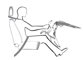
Sitting in the Correct Position

When you use them properly, the seat, head restraint, seatbelt and airbags will provide optimum protection in the event of a crash.
