Ford Escape 2020-2026 Service Manual / Powertrain / Engine / Engine Cooling / Removal and Installation - Transmission Fluid Cooler Coolant Control Valve
Ford Escape: Engine Cooling / Removal and Installation - Transmission Fluid Cooler Coolant Control Valve
Special Tool(s) / General Equipment
| Hose Clamp Remover/Installer |
Removal
NOTE: Removal steps in this procedure may contain installation details.
-
Remove the front bumper cover.
Refer to: Front Bumper Cover (501-19 Bumpers, Removal and Installation).
-


Loosen the pressure relief cap..jpg) WARNING:
When releasing the cooling system pressure, cover
the coolant expansion tank cap with a thick cloth to prevent the
possibility of scalding. Failure to follow this instruction may result
in personal injury.
WARNING:
When releasing the cooling system pressure, cover
the coolant expansion tank cap with a thick cloth to prevent the
possibility of scalding. Failure to follow this instruction may result
in personal injury.
 |
-
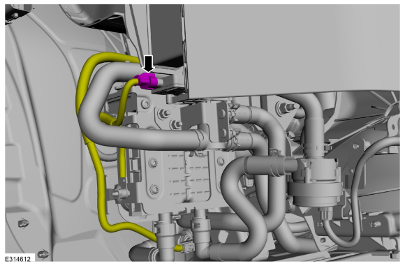
Disconnect the coolant control valve electrical connector.
 |
-
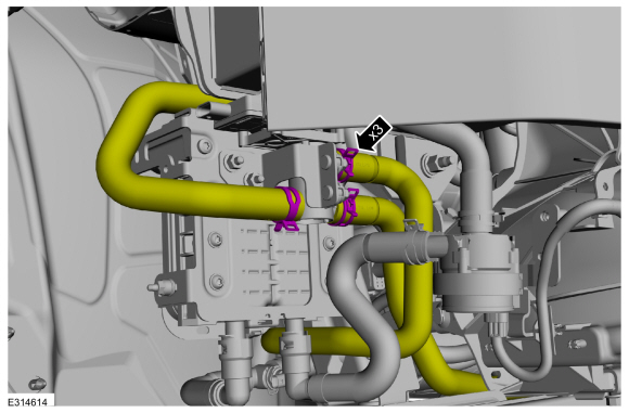
Clamp off the coolant control valve hoses.
.jpg) |
-
Release the clamps and disconnect the coolant hoses.
Use the General Equipment: Hose Clamp Remover/Installer
 |
-
Remove the nuts and the transmission fluid cooler control valve.
Torque: 93 lb.in (10.5 Nm)
.jpg) |
Installation
-
To install, reverse the removal procedure.
-
Fill and bleed the cooling system without using a vacuum cooling system filler.
Refer to: Engine Cooling System Draining, Vacuum Filling and Bleeding (303-03C Engine Cooling, General Procedures).
 Removal and Installation - Thermostat Housing
Special Tool(s) /
General Equipment
Hose Clamp Remover/Installer
Removal
NOTE:
Removal steps in this procedure may contain installation details...

Other information:
Ford Escape 2020-2026 Service Manual: General Procedures - Seatbelt Minder Deactivating/Activating
Activation WARNING: Before beginning any service procedure in this section, refer to Safety Warnings in section 100-00 General Information. Failure to follow this instruction may result in serious personal injury. NOTE: If you are using a MyKey® programmed key, the Belt-Minder® cannot be disabled and does not time out after 5 minutes. If the Belt-Minder® has been previously..
Ford Escape 2020-2026 Service Manual: Removal - Engine
Special Tool(s) / General Equipment 303-476 (T94P-9472-A) Socket, Exhaust Gas Oxygen SensorTKIT-1994-LM/MTKIT-1994-FTKIT-1994-FLM/FM Strap Wrench Floor Crane Adjustable Mounting Arm Oil Drain Equipment Hose Clamp Remover/Installer Fluid Container Punch Powertrain Jack Wooden Block Copper Hammer Materials Name Specification Mot..
Categories
- Manuals Home
- 4th Generation Ford Escape Owners Manual
- 4th Generation Ford Escape Service Manual
- Rear View Camera
- General Procedures - Transmission Fluid Level Check
- Fuel Quality
- New on site
- Most important about car
Vehicle Identification
Locating the Vehicle Identification Number
The vehicle identification number is on the left-hand side of the instrument panel.

Copyright © 2026 www.fordescape4.com