Ford Escape: Engine / Removal and Installation - Valve Cover
Special Tool(s) /
General Equipment
 |
205-153
(T80T-4000-W)
Handle |
 |
303-1247
VCT Spark Plug Tube Seal Remover and Installer
TKIT-2006UF-FLM
TKIT-2006UF-ROW |
Materials
| Name |
Specification |
Motorcraft® High Performance Engine RTV Silicone
TA-357 |
WSE-M4G323-A6
|
Motorcraft® Metal Surface Prep Wipes
ZC-31-B |
-
|
Removal
NOTE:
During engine repair procedures, cleanliness is extremely
important. Any foreign material, including any material created while
cleaning gasket surfaces, that enters the oil passages, coolant passages
or the oil pan can cause engine failure.
-
With the vehicle in NEUTRAL, position it on a hoist.
Refer to: Jacking and Lifting - Overview (100-02 Jacking and Lifting, Description and Operation).
-
Remove the nut, release the engine appearance cover from the ball-studs, then remove the cover.
-
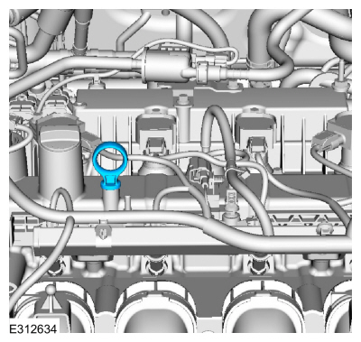
Remove the oil level indicator.
-
Remove the ignition coil-on-plugs.
Refer to: Ignition Coil-On-Plug (303-07C Engine Ignition, Removal and Installation).
-
Disconnect the vent tubes.
Refer to: Quick Release Coupling (310-00G)
.
-
Detach the pin-type retainer, remove the nut and fuel line bracket.
-
Remove the fasteners and undershield.
-
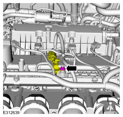
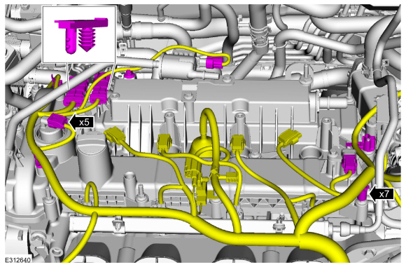
Disconnect the CKP electrical connector and detach the pin-type retainers.
-
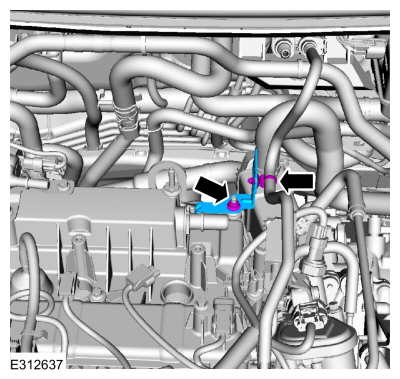
Position out the boot and disconnect the CHT sensor electrical connector.
-
Detach the wire harness retainer.
-
Remove the nut and position aside the radio capacitor.
-
Disconnect the electrical connectors, detach the wire harness retainers and position aside.
-
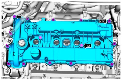
Loosen the fasteners and remove the valve cover.
-
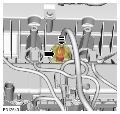
NOTE:
The VCT solenoid seal should only be replaced if it is damaged.
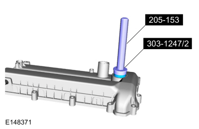
If necessary, using the special tools, remove the VCT seals.
Use Special Service Tool: 303-1247
VCT Spark Plug Tube Seal Remover and Installer.
, 205-153
(T80T-4000-W)
Handle.
-
NOTE:
Do not use metal scrapers, wire brushes, power
abrasive discs or other abrasive means to clean the sealing surfaces.
These tools cause scratches and gouges which make leak paths.
Clean the sealing surfaces.
Material: Motorcraft® Metal Surface Prep Wipes
/ ZC-31-B
Installation
-
NOTE:
Installation of a new VCT seal is required if a damaged seal was removed during disassembly of the engine.
If removed, using the special tools, install the VCT seals.
Use Special Service Tool: 303-1247
VCT Spark Plug Tube Seal Remover and Installer.
, 205-153
(T80T-4000-W)
Handle.
-
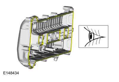
Inspect and if necessary, install new valve cover gaskets.
-
NOTE:
The valve cover must be secured within 10 minutes of
silicone gasket application. If the valve cover is not secured within
10 minutes, the sealant must be removed and the sealing area cleaned
with metal surface prep.
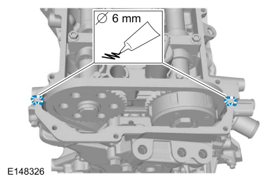
Apply a 6 mm bead of silicone sealant.
Material: Motorcraft® High Performance Engine RTV Silicone
/ TA-357
(WSE-M4G323-A6)
-
Install the valve cover and tighten the fasteners in sequence shown.
Torque:
89 lb.in (10 Nm)
-
Position back the wire harness, connect the electrical connectors and attach the retainers.
-
Position the radio capacitor and install the nut.
Torque:
89 lb.in (10 Nm)
-
Attach the wire harness retainer.
-
Connect the CHT sensor electrical connector and position back the boot.
-
Connect the CKP electrical connector and attach the pin-type retainers.
-
Install the undershield and fasteners.
-
Install the fuel line bracket, nut and attach the pin-type retainer.
-
Connect the vent tubes.
Refer to: Quick Release Coupling (310-00G)
.
-
Install the ignition coil-on-plugs.
Refer to: Ignition Coil-On-Plug (303-07C Engine Ignition, Removal and Installation).
-
Install the oil level indicator.
-
Install the engine appearance cover to the ball-studs, then install and tighten the nut.
Torque:
97 lb.in (11 Nm)
Removal
NOTICE:
Do not loosen or remove the crankshaft pulley bolt without
first installing the special tools as instructed in this procedure. The
crankshaft pulley and the crankshaft timing sprocket are not keyed to
the crankshaft...
Removal
Remove the camshafts.
Refer to: Camshafts (303-01B Engine - 2.0L EcoBoost (177kW/240PS) – MI4, Removal and Installation).
If the camshafts and valve tappets are to be reused,
make sure they are assembled in their original positions...
Other information:
Overview
The generator is driven by the FEAD belt. When the engine is
started, the generator begins to generate AC voltage which is internally
converted to DC voltage. The DC voltage is controlled by the voltage
regulator and supplied to the battery...
Special Tool(s) /
General Equipment
205-153
(T80T-4000-W)
Handle
307-758Installer, Axle Seal -FWD
Flat Headed Screw Driver
Removal
Remove the power transfer unit.
Refer to: Power Transfer Unit (308-07E)
.
Remove and discard the RH halfshaft seal...
.jpg)
.jpg)
.jpg)
.jpg)
.jpg)
.jpg)
.jpg)
.jpg)
.jpg)
 Removal and Installation - Timing Chain Tensioner
 Removal and Installation - Valve Tappets