Ford Escape: Rear End Sheet Metal Repairs / Removal and Installation - Water Drain Panel
Special Tool(s) / General Equipment
| Resistance Spotwelding Equipment | |
| Hot Air Gun | |
| 8 mm Drill Bit | |
| MIG/MAG Welding Equipment | |
| Spot Weld Drill Bit | |
| Locking Pliers |
Materials
| Name | Specification |
|---|---|
| Metal Bonding Adhesive TA-1, TA-1-B, 3M™ 08115, LORD Fusor® 108B, Henkel Teroson EP 5055 |
- |
| Flexible Foam Repair 3M™ 08463, LORD Fusor® 121 |
- |
Removal
.jpg) WARNING:
Electric vehicles damaged by a crash may have compromised
high voltage safety systems and present a potential high voltage
electrical shock hazard. Exercise caution and wear appropriate Personal
Protective Equipment (PPE) safety gear, including high voltage safety
gloves and boots. Remove all metallic jewelry, including watches and
rings. Isolate the HV system as directed by the Ford Emergency Response
Guide for the vehicle. Failure to follow these instructions may result
in serious personal injury or death.
WARNING:
Electric vehicles damaged by a crash may have compromised
high voltage safety systems and present a potential high voltage
electrical shock hazard. Exercise caution and wear appropriate Personal
Protective Equipment (PPE) safety gear, including high voltage safety
gloves and boots. Remove all metallic jewelry, including watches and
rings. Isolate the HV system as directed by the Ford Emergency Response
Guide for the vehicle. Failure to follow these instructions may result
in serious personal injury or death.
NOTICE: Battery electric vehicle (BEV), hybrid electric vehicle (HEV) and plug-in hybrid electric vehicle (PHEV) contain a high-voltage battery. Before cutting or welding near the high-voltage battery it must be removed to avoid damage.
NOTE: Left hand (LH) side shown, right hand (RH) side similar.
NOTE: The water drain trough is constructed of dual phase (DP) 800 steel. No sectioning is permitted. However, the drain panel assembly is made of multiple components and may be separated at factory seams. The following assumes full component replacement. Adjust to meet repair needs.
-
Refer to: Health and Safety Precautions (100-00 General Information, Description and Operation).
WARNING:
Before beginning any service procedure in this
manual, refer to health and safety warnings in section 100-00 General
Information. Failure to follow this instruction may result in serious
personal injury.
Refer to: High Voltage System Health and Safety Precautions - Overview (100-00 General Information, Description and Operation).
-
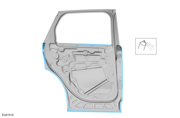
Water Drain Panel Overview
.jpg) |
-
If Necessary:
Dimensionally restore the vehicle to pre-damage condition.
Refer to: Body and Frame (501-26 Body Repairs - Vehicle Specific Information and Tolerance Checks, Description and Operation).
-
Remove the liftgate.
Refer to: Liftgate (501-03 Body Closures, Removal and Installation).
-
Remove the liftgate support bracket and body plug.
.jpg) |
-
Remove the liftgate bumper.
.jpg) |
-
Remove the roof.
Refer to: Roof Panel (501-28 Roof Sheet Metal Repairs, Removal and Installation).
-
Remove the roof rear header.
Refer to: Roof Rear Frame (501-28 Roof Sheet Metal Repairs, Removal and Installation).
-
Remove the quarter panel.
Refer to: Quarter Panel (501-30 Rear End Sheet Metal Repairs, Removal and Installation).
-
Remove the air vent.
.jpg) |
-
Remove the outer back panel only.
Refer to: Back Panel and Reinforcement (501-30 Rear End Sheet Metal Repairs, Removal and Installation).
-
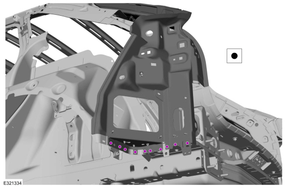
Remove the welds.
Use the General Equipment: Spot Weld Drill Bit
.jpg) |
-
Remove the welds.
Use the General Equipment: Spot Weld Drill Bit
.jpg) |
-
Remove the welds.
Use the General Equipment: Spot Weld Drill Bit
.jpg) |
-
NOTE: Pay particular attention to the location of adhesives, sealers and NVH materials to aid in installation.
Remove the water drain panel.
Use the General Equipment: Hot Air Gun
.jpg) |
Installation
WARNING:
Electric vehicles damaged by a crash may have compromised
high voltage safety systems and present a potential high voltage
electrical shock hazard. Exercise caution and wear appropriate Personal
Protective Equipment (PPE) safety gear, including high voltage safety
gloves and boots. Remove all metallic jewelry, including watches and
rings. Isolate the HV system as directed by the Ford Emergency Response
Guide for the vehicle. Failure to follow these instructions may result
in serious personal injury or death.
NOTICE: Battery electric vehicle (BEV), hybrid electric vehicle (HEV) and plug-in hybrid electric vehicle (PHEV) contain a high-voltage battery. Before cutting or welding near the high-voltage battery it must be removed to avoid damage.
NOTICE: The high-voltage battery in a battery electric vehicle (BEV), hybrid electric vehicle (HEV) or plug-in hybrid electric vehicle (PHEV) can be affected and damaged by excessively high temperatures. The temperature in some body shop paint booths can exceed 60° C (140° F). Therefore, during refinishing operations, the paint booth temperature must set at or below 60° C (140° F) with a bake time of 45 minutes or less. Temperatures in excess of 60° C (140° F) or bake durations longer than 45 minutes will require the high-voltage battery be removed from the vehicle prior to placing in the paint booth.
NOTICE: If refinishing cure temperatures exceed 60° C (140° F), the charge port light ring on plug-in vehicles must be removed.
NOTE: Factory welds may be substituted with resistance or metal inert gas (MIG) plug welds. Resistance welds may not be placed directly over original location. They must be placed adjacent to original location and match factory welds in quantity. Metal inert gas (MIG) plug welds must equal factory welds in both location and quantity.
NOTE: Left hand (LH) side shown, right hand (RH) side similar.
-
Refer to: Health and Safety Precautions (100-00 General Information, Description and Operation).
WARNING:
Before beginning any service procedure in this
manual, refer to health and safety warnings in section 100-00 General
Information. Failure to follow this instruction may result in serious
personal injury.
Refer to: High Voltage System Health and Safety Precautions - Overview (100-00 General Information, Description and Operation).
-
Using a hammer and dolly, straighten any damage to the vehicle caused during removal.
-
Drill plug weld holes.
Use the General Equipment: 8 mm Drill Bit
 |
-
Sand to remove old adhesive and clean.
.jpg) |
-
Apply adhesive.
Material: Metal Bonding Adhesive / TA-1, TA-1-B, 3M™ 08115, LORD Fusor® 108B, Henkel Teroson EP 5055
.jpg) |
-
Install, properly position and clamp the panel.
Use the General Equipment: Locking Pliers
.jpg) |
-
Install the welds.
Use the General Equipment: Resistance Spotwelding Equipment
.jpg) |
-
Install the welds.
Use the General Equipment: Resistance Spotwelding Equipment
.jpg) |
-
Install the welds.
Use the General Equipment: Resistance Spotwelding Equipment
 |
-
Install the welds.
Use the General Equipment: MIG/MAG Welding Equipment
.jpg) |
-
Install NVH foam sealant in areas noted during removal.
Material: Flexible Foam Repair / 3M™ 08463, LORD Fusor® 121
.jpg) |
-
Install the air vent.
|
-
Install the quarter panel.
Refer to: Quarter Panel (501-30 Rear End Sheet Metal Repairs, Removal and Installation).
-
Install the rear header panel.
Refer to: Roof Rear Frame (501-28 Roof Sheet Metal Repairs, Removal and Installation).
-
Install the roof.
Refer to: Roof Panel (501-28 Roof Sheet Metal Repairs, Removal and Installation).
-
Refinish the entire repair using a Ford approved paint system.
-
Restore corrosion protection.
Refer to: Corrosion Prevention (501-25 Body Repairs - General Information, General Procedures).
-
Install the liftgate support bracket and body plug.
Torque: 16 lb.ft (22 Nm)
|
-
Install the lift gate bumper.
|
-
Install the rear bumper and bumper cover.
Refer to: Rear Bumper (501-19 Bumpers, Removal and Installation).
Refer to: Rear Bumper Cover (501-19 Bumpers, Removal and Installation).
-
Install the tail lamp assembly.
Refer to: Rear Lamp Assembly (417-01 Exterior Lighting, Removal and Installation).
-
Install and align the liftgate.
Refer to: Liftgate (501-03 Body Closures, Removal and Installation).
Refer to: Liftgate Alignment (501-03 Body Closures, General Procedures).
-
Repower the SRS .
Refer to: Supplemental Restraint System (SRS) Repowering (501-20B Supplemental Restraint System, General Procedures).


Other information:
Ford Escape 2020-2026 Owners Manual: Creating a MyKey - Vehicles With: Push Button Start. Creating a MyKey - Vehicles With: Flip Key
Creating a MyKey - Vehicles With: Push Button Start Remove the mat covering the backup location. Remove the key blade from the transmitter. Place the passive key in the position shown, with the buttons facing upward. Switch the ignition on. Using your touchscreen, press Menu. Press Settings. Press Vehicle. Press MyKey. Press Create MyKey. Press Yes if you want to create the key..
Ford Escape 2020-2026 Service Manual: Removal and Installation - Front Seat Power Lumbar Assembly
Removal NOTE: Driver seat shown, passenger seat similar. Remove the front seat backrest cover. Refer to: Front Seat Backrest Cover (501-10A Front Seats, Removal and Installation). Remove the front seat power lumbar assembly. Disconnect the electrical connector. Detach the upper J-hooks. Detach the middle J-hooks. Detach the low..
Categories
- Manuals Home
- 4th Generation Ford Escape Owners Manual
- 4th Generation Ford Escape Service Manual
- Symbols Glossary
- Adjusting the Headlamps
- Power Outlet - Vehicles With: 12V Power Outlet
- New on site
- Most important about car
Fastening the Seatbelts
