Ford Escape: Automatic Transmission - Automatic Transmission – HF45 / Assembly - Transmission
Special Tool(s) / General Equipment
 |
204-029 Drawbar |
 |
205-153
(T80T-4000-W)
Handle |
 |
307-541 Installer, Transfer Gear Bearing TKIT-2005D1-F |
 |
307-591 Shim Gauge, Differential/Transfer Gear Bearing TKIT-2006UF-FLM TKIT-2006UF-ROW |
.jpg) |
307-672 Installer, Input Guide and Seal TKIT-2010D-FLM TKIT-2010D-ROW |
 |
307-680 Table, Assembly (DPS6) TKIT-2010D-FLM TKIT-2010D-ROW |
 |
307-741 Spring Compressor, F Clutch |
 |
307-758 Installer, Axle Seal -FWD |
 |
307-759 Installer, Axle Seal -AWD |
 |
307-792 Gauge, Differential Preload |
 |
307-793 Installer, Bearing Cup |
 |
307-794 Transfer gear shim preload tool |
 |
307-795 Installer, Bearing Cup |
 |
307-821 Motor Rotor Remover Installer |
| Feeler Gauge | |
| Hydraulic Press | |
Materials
| Name | Specification |
|---|---|
| Motorcraft® MERCON® ULV Automatic Transmission Fluid XT-12-QULV |
WSS-M2C949-A, MERCON® ULV |
| Motorcraft® Ultra Silicone Sealant TA-29 |
WSS-M4G323-A8 |
All vehicles
-
-
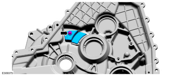
Install the park lock actuator guide and park pawl.
-
Install the park lock actuator guide bolts.
Torque: 89 lb.in (10 Nm)
-
Install the park pawl shaft.
-
Install the park lock actuator guide and park pawl.
 |
-
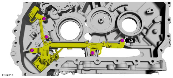
Install the fluid pump and filter assembly.
Torque: 89 lb.in (10 Nm)
 |
-
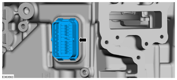
Install the wiring harness bulkhead connector into the transmission case.
 |
-
Install the wiring harness bolts.
Torque: 89 lb.in (10 Nm)
 |
-
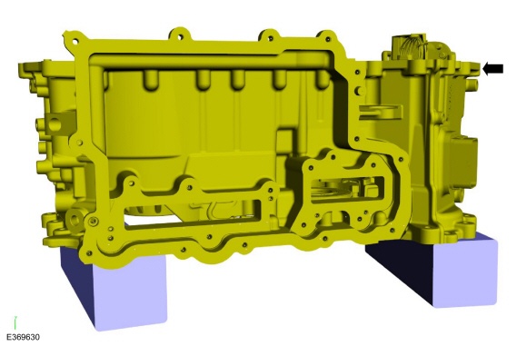
Position the transmission case on blocks of wood.
 |
-
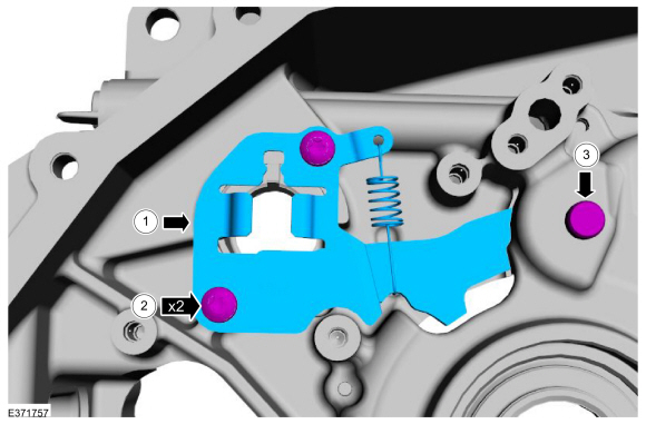
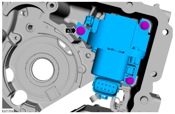
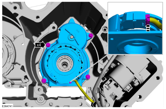
NOTE: Make sure park rod is installed in the park rod guide.
Install the park lock actuator and the bolts.
Torque: 97 lb.in (11 Nm)
 |
-
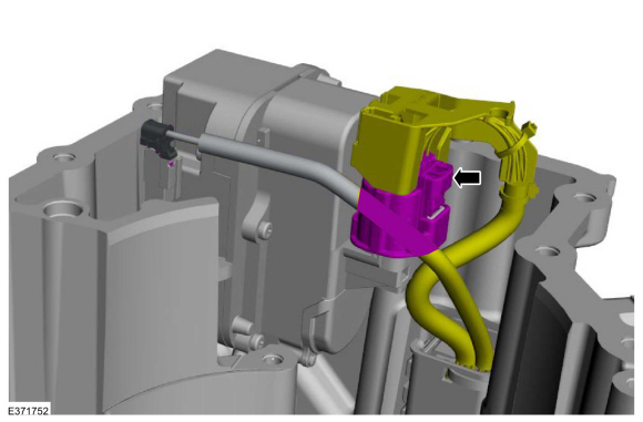
Connect the park lock actuator electrical connector.
 |
-
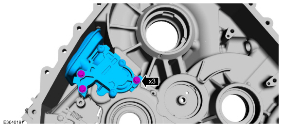
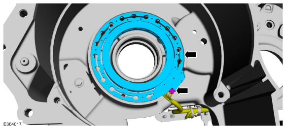
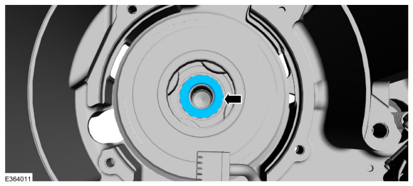
If removed during disassembly, connect and install the traction motor resolver.
 |
-
NOTICE: Resolver realignment is critical to transmission calibration and operation.
Install the traction motor resolver bolts and align the index-marks made during removal.
Torque: 71 lb.in (8 Nm)
.jpg) |
-
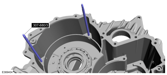
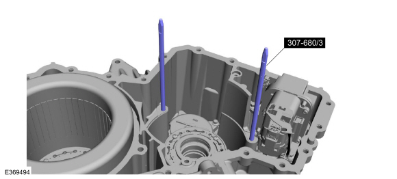
Install the special tools in the traction motor stator bolt holes.
Use Special Service Tool: 307-680 Table, Assembly (DPS6).
 |
-
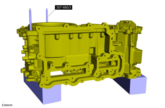
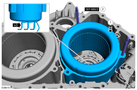
NOTICE: When installing the stator be careful not to bend or break the stator wires.
Position the traction motor stator on the special tools and install the stator.
Use Special Service Tool: 307-680 Table, Assembly (DPS6).
.jpg) |
-
Position the transmission case back on the wooden blocks and remove the special tools.
Use Special Service Tool: 307-680 Table, Assembly (DPS6).
 |
-
Install the ring gear and bearing.
 |
-
Install the planetary carrier assembly.
 |
-
Install the sun gear thrust bearing.
 |
-
Install the sun gear.
 |
-
Install the pump drive gear.
.jpg) |
-
Install the thrust washer from the planetary carrier support cover.
 |
-
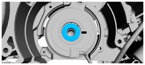
Connect the generator/starter resolver, install the planetary carrier support cover and the bolts.
Torque: 97 lb.in (11 Nm)
 |
-
Install the special tools in the generator/starter stator bolt holes.
Use Special Service Tool: 307-680 Table, Assembly (DPS6).
 |
-
NOTICE: When installing the stator be careful not to bend or break the stator wires.
-
Position the generator/starter stator on the special tools and install the stator.
-
Remove the special tools.
Use Special Service Tool: 307-680 Table, Assembly (DPS6).
-
Position the generator/starter stator on the special tools and install the stator.
 |
-
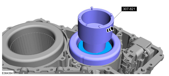
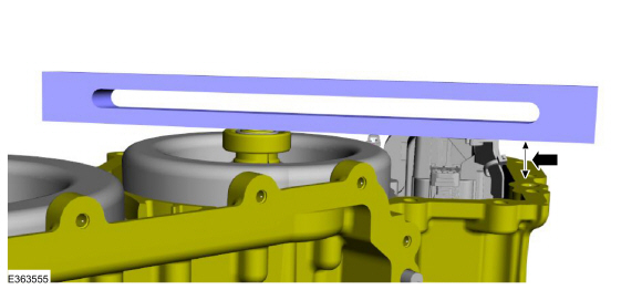
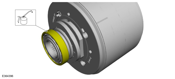
Install the special tool on the generator/starter stator windings.
Use Special Service Tool: 307-821 Motor Rotor Remover Installer.
.jpg) |
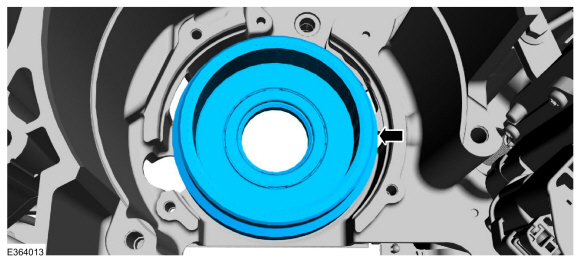
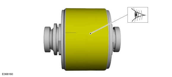
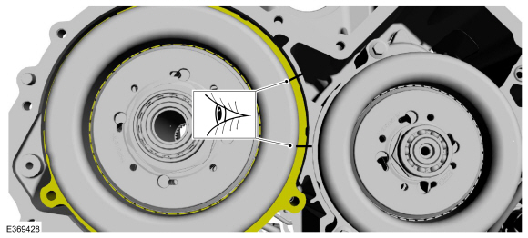
-
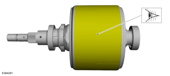
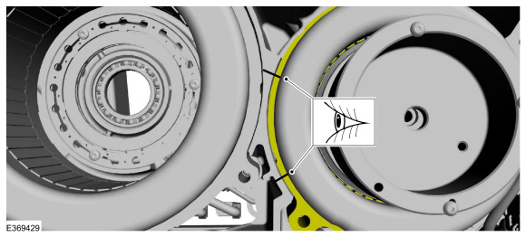
Inspect the surface of the generator/starter rotor for
raised metal due to scratches and scuff marks. Remove all raised metal
with a very fine grit sand paper.
 |
-
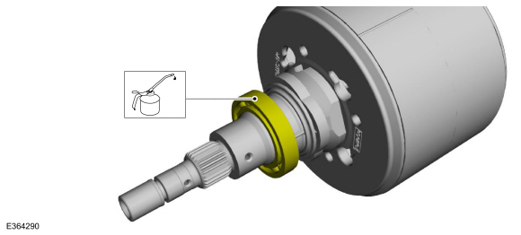
Lubricate the generator/starter bearing surface.
Material: Motorcraft® MERCON® ULV Automatic Transmission Fluid / XT-12-QULV (WSS-M2C949-A, ) (MERCON® ULV)
 |
-
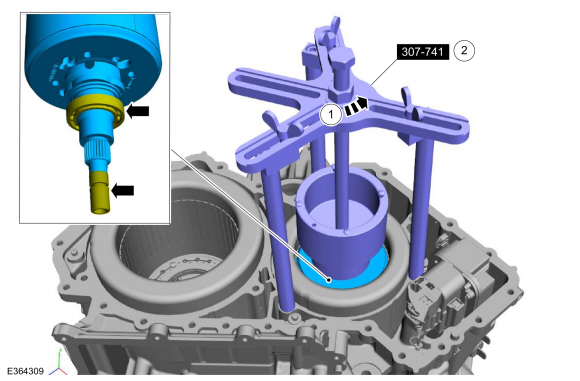
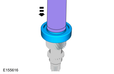
NOTE: When installing the generator/starter rotor, the shaft on the rotor needs to align with the input shaft and the bearing needs to align with the bore in the planetary carrier support cover.
Using the special tools, install the generator/starter rotor.
-
Turn the nut on the drawbar counter-clockwise while
holding the drawbar so it doesn't rotate out of the rotor.
-
When the rotor won't lower anymore, remove the special tool 307-741.
-
Turn the nut on the drawbar counter-clockwise while
holding the drawbar so it doesn't rotate out of the rotor.
 |
-
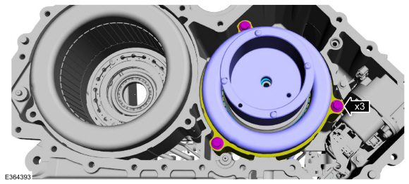
Align the generator/starter stator to transmission case index-marks made during removal.
 |
-
Install the generator/starter stator bolts.
Torque: 18 lb.ft (25 Nm)
 |
-
Rotate the special tool until the generator/starter rotor is completely installed.
Use Special Service Tool: 307-821 Motor Rotor Remover Installer.
 |
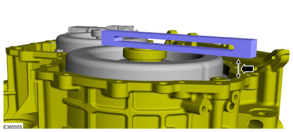
-
Check measurement recorded on disassembly to verify generator/starter rotor is completely installed.
 |
-
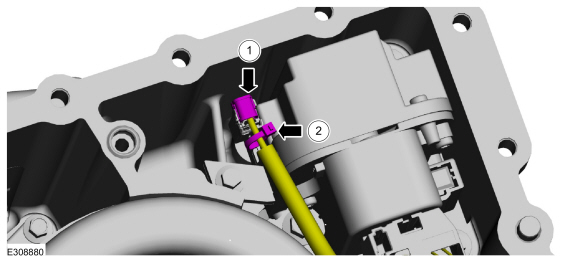
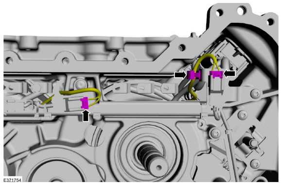
-
Connect the park lock actuator.
-
Install a new tie strap.
-
Connect the park lock actuator.
 |
-
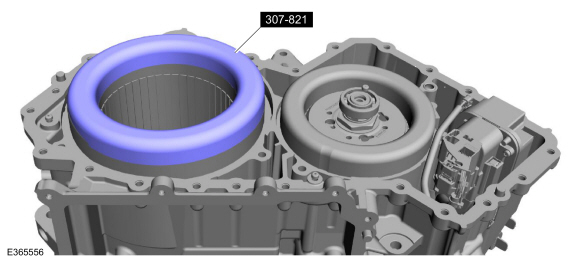
Install the special tool on the traction motor stator windings.
Use Special Service Tool: 307-821 Motor Rotor Remover Installer.
 |
-
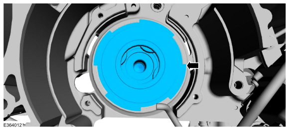
Inspect the surface of the traction rotor for raised
metal due to scratches and scuff marks. Remove all raised metal with a
very fine grit sand paper.
 |
-
Lubricate the traction motor bearing surface.
Material: Motorcraft® MERCON® ULV Automatic Transmission Fluid / XT-12-QULV (WSS-M2C949-A, ) (MERCON® ULV)
 |
-
Using the special tools, install the traction motor rotor.
-
Turn the nut on the drawbar counter-clockwise while
holding the drawbar so it doesn't rotate out of the rotor.
Use Special Service Tool: 307-741 Spring Compressor, F Clutch. , 307-821 Motor Rotor Remover Installer.
-
Lower the rotor until the bottom of the tapered edge
on the rotor is even with the top edge of the stator core.
-
Turn the nut on the drawbar counter-clockwise while
holding the drawbar so it doesn't rotate out of the rotor.
.jpg) |
-
Align the traction motor stator to transmission case index-marks made during removal.
 |
-
Install the traction motor stator bolts.
Torque: 18 lb.ft (25 Nm)
.jpg) |
-
Check measurement recorded on disassembly to verify the traction motor rotor is completely installed.
 |
-
Install the transmission case cover.
Refer to: Transmission Case Cover (307-01B Automatic Transmission - Automatic Transmission – HF45, Removal and Installation).
-
-
Connect the traction motor stator electrical connector.
-
Connect the generator/starter stator electrical connector.
-
Attach the wiring retainer.
-
Connect the traction motor stator electrical connector.
 |
-
Install the transmission high voltage terminals.
Refer to: Transmission High Voltage Terminals (307-01B Automatic Transmission - Automatic Transmission – HF45, Disassembly and Assembly of Subassemblies).
-
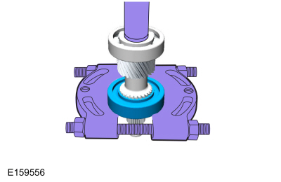
NOTICE: When installing the bearing make sure to only press on the inner bearing race or damage may occur to the bearing.
Press the traction motor drive gear front bearing on the traction motor drive gear.
Use the General Equipment: Hydraulic Press
 |
-
Press the traction motor drive gear rear bearing on the traction motor drive gear.
Use the General Equipment: Hydraulic Press
 |
-
NOTICE: Do not use metal scrapers, wire brushes, power abrasive discs, or other abrasive means to clean sealing surfaces. These tools cause scratches and gouges which make leak paths.
Make sure that the mating faces are clean and free of foreign material.
Refer to: RTV Sealing Surface Cleaning and Preparation (303-00 Engine System - General Information, General Procedures).
 |
-
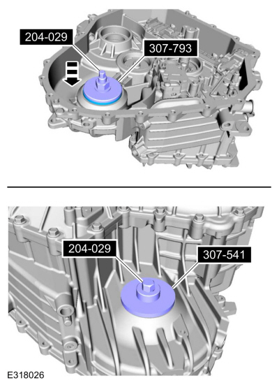
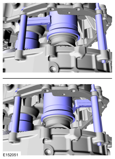
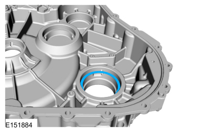
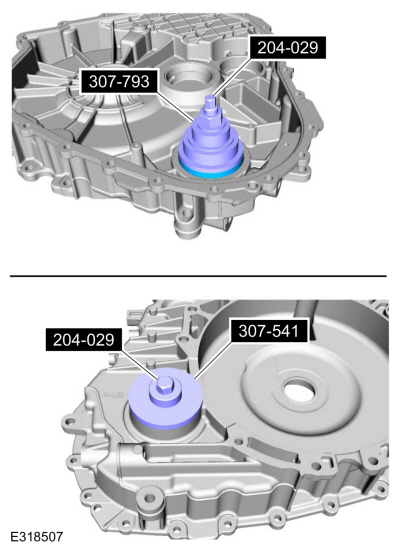
Using the special tool, install the transmission case side differential bearing cup.
Use Special Service Tool: 204-029 Drawbar. , 307-793 Installer, Bearing Cup. , 307-541 Installer, Transfer Gear Bearing.
 |
-
Using the special tool, install the transmission case side transfer shaft bearing cup.
Use Special Service Tool: 205-153 (T80T-4000-W) Handle. , 307-795 Installer, Bearing Cup.
.jpg) |
-
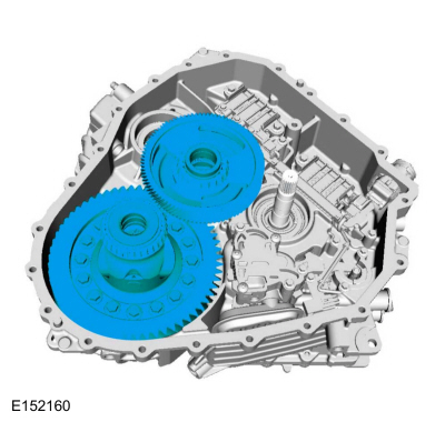
Install the transfer shaft gear assembly and the differential carrier gear assembly.
 |
-
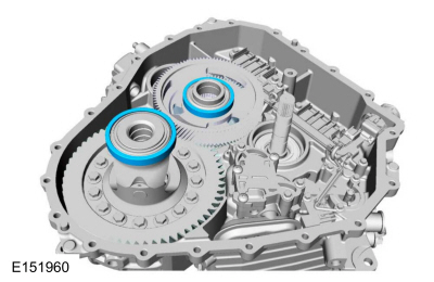
Place the differential bearing cup and the transfer shaft bearing cup on the bearings.
 |
-
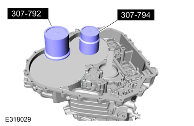
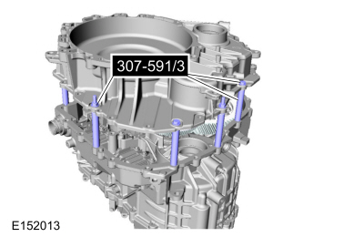
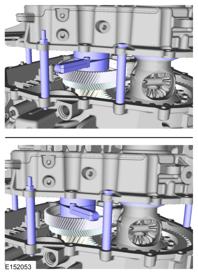
Install the special tools on top of the bearing cups.
Use Special Service Tool: 307-792 Gauge, Differential Preload. , 307-794 Transfer gear shim preload tool.
 |
-
Install the special tools, placing the spacers on the studs.
Use Special Service Tool: 307-591 Shim Gauge, Differential/Transfer Gear Bearing.
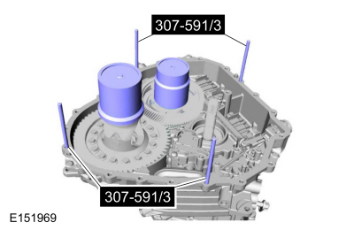 |
-
NOTE: Make sure that the silicone has been cleaned off the machined surface of the transmission case and the damper housing before installing the Differential/Transfer Gear Bearing Shim Gauge 307-591/3 (4 spacers) or the preload measurement may be inaccurate.
Use Special Service Tool: 307-591 Shim Gauge, Differential/Transfer Gear Bearing.
 |
-
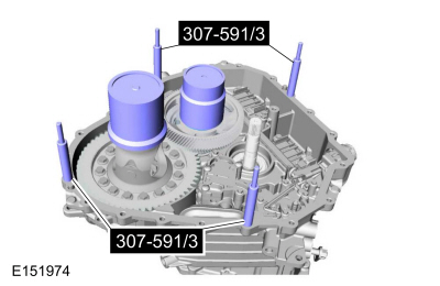
Install the damper housing on the special tools.
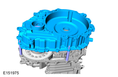 |
-
Install the special tools by installing the nuts on the studs.
Use Special Service Tool: 307-591 Shim Gauge, Differential/Transfer Gear Bearing.
Torque: 18 lb.ft (24 Nm)
 |
-
Rotate the transfer shaft and the differential several times to seat the bearing cups.
.jpg) |
-
Measure and record the smallest and largest preload gap
on the Shim Gauge, Differential/Transfer Gear Bearing 307-591/1. Average
the 2 measurements then add .16 mm to get the thickness of the
differential bearing preload shim. For the differential bearing preload
shim part number.
Refer to: Specifications (307-01B Automatic Transmission - Automatic Transmission – HF45, Specifications).
Use the General Equipment: Feeler Gauge
 |
-
Measure and record the smallest and largest preload gap
on the Transfer Gear Preload Tool 307-692. Average the 2 measurements
then add .15 mm to get the thickness of the transfer gear bearing
preload shim. For the transfer bearing preload shim part number.
Refer to: Specifications (307-01B Automatic Transmission - Automatic Transmission – HF45, Specifications).
Use the General Equipment: Feeler Gauge
 |
-
Install the transfer shaft preload shim.
 |
-
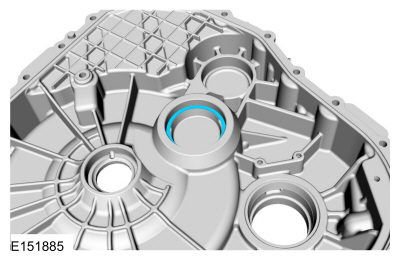
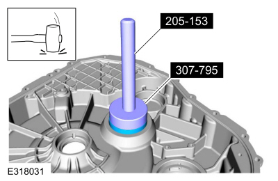
Using the special tools, install the damper housing side transfer gear bearing cup.
Use Special Service Tool: 307-795 Installer, Bearing Cup. , 205-153 (T80T-4000-W) Handle.
 |
-
Install the differential preload shim.
 |
-
Using the special tools, install the damper housing side differential bearing cup.
Use Special Service Tool: 204-029 Drawbar. , 307-541 Installer, Transfer Gear Bearing. , 307-793 Installer, Bearing Cup.
 |
-
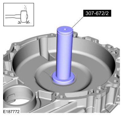
Using the special tool, install the input shaft seal.
Use Special Service Tool: 307-672 Installer, Input Guide and Seal.
 |
All Wheel Drive (AWD)
-
Using the special tool, install the RH halfshaft seal.
Use Special Service Tool: 307-759 Installer, Axle Seal -AWD. , 205-153 (T80T-4000-W) Handle.
 |
Front Wheel Drive (FWD)
-
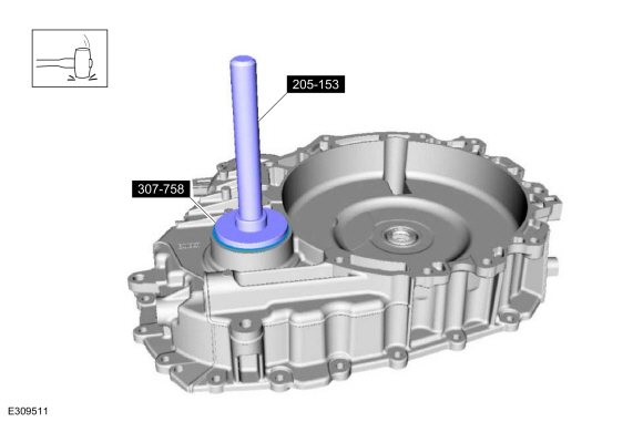
Using the special tool, install the RH halfshaft seal.
Use Special Service Tool: 307-758 Installer, Axle Seal -FWD. , 205-153 (T80T-4000-W) Handle.
 |
All vehicles
-
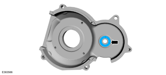
Remove the transmission fluid collector plate and the retainer.
Torque: 97 lb.in (11 Nm)
 |
-
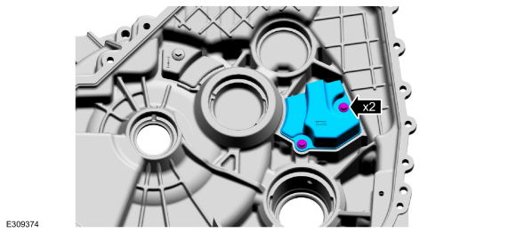
Install the transmission fluid collector plate and the retainers.
Torque: 97 lb.in (11 Nm)
 |
-
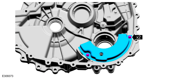
Install the transmission fluid sump baffle and the retainers.
Torque: 97 lb.in (11 Nm)
 |
-
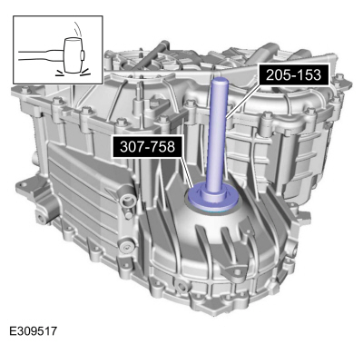
Using the special tool, install the LH halfshaft seal.
Use Special Service Tool: 205-153 (T80T-4000-W) Handle. , 307-758 Installer, Axle Seal -FWD.
 |
-
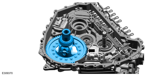
Install the differential carrier gear assembly.
 |
-
Install the final drive input gear assembly.
.jpg) |
-
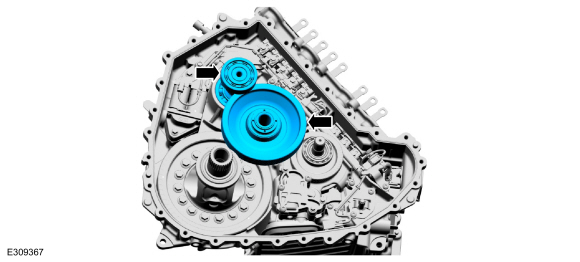
Install the transfer shaft gear assembly and the traction motor drive gear assembly.
 |
-
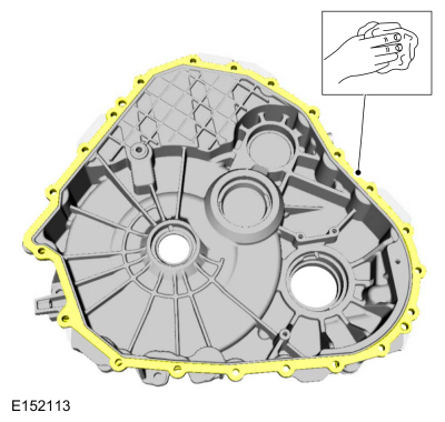
Prepare the case sealing surfaces.
Refer to: RTV Sealing Surface Cleaning and Preparation (303-00 Engine System - General Information, General Procedures).
-
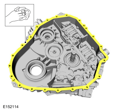
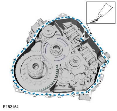
NOTE: Make sure silicone is applied to the shoulder on the inner bolt hole.
Apply silicone to the transmission case assembly.
Material: Motorcraft® Ultra Silicone Sealant / TA-29 (WSS-M4G323-A8)
 |
-
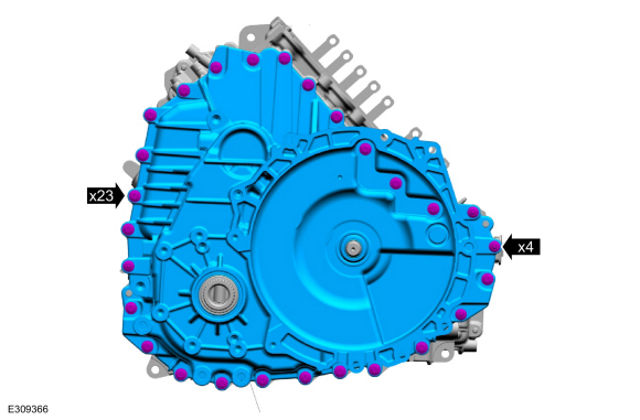
NOTE: Install the stud bolts in the locations noted during disassembly.
NOTE: Tighten in a crisscross pattern.
Install the damper housing, bolts and the studbolts.
Torque: 18 lb.ft (25 Nm)
 |
-
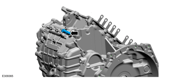
Install the vent assembly.
 |
 Disassembly and Assembly of Subassemblies - Transmission High Voltage Terminals
DISASSEMBLY
Disconnect the high voltage inductor.
Remove the bolts and the high voltage inductor.
Remove the high voltage bolts...
 Assembly - Transmission - Plug-In Hybrid Electric Vehicle (PHEV)
Special Tool(s) /
General Equipment
204-029Drawbar
205-153
(T80T-4000-W)
Handle
307-541Installer, Transfer Gear BearingTKIT-2005D1-F
307-591Shim Gauge, Differential/Transfer Gear BearingTKIT-2006UF-FLMTKIT-2006UF-ROW
307-672Installer, Input Guide and SealTKIT-2010D-FLMTKIT-2010D-ROW
307-680Table, Assembly (DPS6)TKIT-2010D-FLMTKIT-2010D-ROW
307-741..
Other information:
Ford Escape 2020-2026 Service Manual: Removal and Installation - Catalytic Converter - Hybrid Electric Vehicle (HEV), FWD
Special Tool(s) / General Equipment Wooden Block Removal NOTE: If the catalytic converter is not being replaced, the HO2S and the catalyst monitor sensor do not need to be removed from the catalytic converter. Disconnecting the electrical connectors is still necessary. NOTE: Removal steps in this procedure may contain installation details. With the vehicle in NEU..
Ford Escape 2020-2026 Owners Manual: Tips for use of the kit. What to do when a tire is punctured
Tips for use of the kit To ensure safe operation of the kit: Before operating the kit, make sure your vehicle is safely off the road and away from moving traffic. Do not remove any foreign objects, such as nails or screws, from the tire. Do not allow the compressor to operate continuously for more than 15 minutes. This will help prevent the compressor from overheating. Only use th..
Categories
- Manuals Home
- 4th Generation Ford Escape Owners Manual
- 4th Generation Ford Escape Service Manual
- Switching the Rear Window Wiper On and Off. Reverse Wipe
- Drive Modes
- All-Wheel Drive
- New on site
- Most important about car
Fastening the Seatbelts
