Ford Escape: Anti-Lock Brake System (ABS) and Stability Control / Diagnosis and Testing - Anti-Lock Brake System (ABS) and Stability Control
Diagnostic Trouble Code (DTC) Chart
Diagnostics in this manual assume a certain skill level and knowledge of Ford-specific diagnostic practices.
REFER to: Diagnostic Methods (100-00 General Information, Description and Operation).
| Module | DTC | Description | Action |
|---|---|---|---|
| ABS | B10DA:51 | PATS Target Identifier: Not Programmed | GO to Pinpoint Test P |
| ABS | C0001:01 | TCS Control Channel 'A' Valve 1: General Electrical Failure | GO to Pinpoint Test Y |
| ABS | C0002:01 | TCS Control Channel 'A' Valve 2: General Electrical Failure | GO to Pinpoint Test Y |
| ABS | C0003:01 | TCS Control Channel 'B' Valve 1: General Electrical Failure | GO to Pinpoint Test Y |
| ABS | C0004:01 | TCS Control Channel 'B' Valve 2: General Electrical Failure | GO to Pinpoint Test Y |
| ABS | C0020:11 | ABS Pump Motor Control: Circuit Short To Ground | GO to Pinpoint Test H |
| ABS | C0020:12 | ABS Pump Motor Control: Circuit Short To Battery | GO to Pinpoint Test H |
| ABS | C0020:13 | ABS Pump Motor Control: Circuit Open | GO to Pinpoint Test H |
| ABS | C0020:49 | ABS Pump Motor Control: Internal Electronic Failure | GO to Pinpoint Test H |
| ABS | C0020:71 | ABS Pump Motor Control: Actuator Stuck | GO to Pinpoint Test H |
| ABS | C0030:07 | Left Front Tone Wheel: Mechanical Failures | GO to Pinpoint Test AB |
| ABS | C0031:01 | Left Front Wheel Speed Sensor: General Electrical Failure | GO to Pinpoint Test M |
| ABS | C0031:07 | Left Front Wheel Speed Sensor: Mechanical Failures | GO to Pinpoint Test AB |
| ABS | C0031:2F | Left Front Wheel Speed Sensor: Signal Erratic | GO to Pinpoint Test AB |
| ABS | C0031:4A | Left Front Wheel Speed Sensor: Incorrect Component Installed | GO to Pinpoint Test AL |
| ABS | C0031:64 | Left Front Wheel Speed Sensor: Signal Plausibility Failure | GO to Pinpoint Test AB |
| ABS | C0033:07 | Right Front Tone Wheel: Mechanical Failures | GO to Pinpoint Test AB |
| ABS | C0034:01 | Right Front Wheel Speed Sensor: General Electrical Failure | GO to Pinpoint Test M |
| ABS | C0034:07 | Right Front Wheel Speed Sensor: Mechanical Failures | GO to Pinpoint Test AB |
| ABS | C0034:2F | Right Front Wheel Speed Sensor: Signal Erratic | GO to Pinpoint Test AB |
| ABS | C0034:4A | Right Front Wheel Speed Sensor: Incorrect Component Installed | GO to Pinpoint Test AL |
| ABS | C0034:64 | Right Front Wheel Speed Sensor: Signal Plausibility Failure | GO to Pinpoint Test AB |
| ABS | C0036:07 | Left Rear Tone Wheel: Mechanical Failures | GO to Pinpoint Test AB |
| ABS | C0037:01 | Left Rear Wheel Speed Sensor: General Electrical Failure | GO to Pinpoint Test N |
| ABS | C0037:07 | Left Rear Wheel Speed Sensor: Mechanical Failures | GO to Pinpoint Test AB |
| ABS | C0037:2F | Left Rear Wheel Speed Sensor: Signal Erratic | GO to Pinpoint Test AB |
| ABS | C0037:4A | Left Rear Wheel Speed Sensor: Incorrect Component Installed | GO to Pinpoint Test AL |
| ABS | C0037:64 | Left Rear Wheel Speed Sensor: Signal Plausibility Failure | GO to Pinpoint Test AB |
| ABS | C0039:07 | Right Rear Tone Wheel: Mechanical Failures | GO to Pinpoint Test AB |
| ABS | C003A:01 | Right Rear Wheel Speed Sensor: General Electrical Failure | GO to Pinpoint Test N |
| ABS | C003A:07 | Right Rear Wheel Speed Sensor: Mechanical Failures | GO to Pinpoint Test AB |
| ABS | C003A:2F | Right Rear Wheel Speed Sensor: Signal Erratic | GO to Pinpoint Test AB |
| ABS | C003A:4A | Right Rear Wheel Speed Sensor: Incorrect Component Installed | GO to Pinpoint Test AL |
| ABS | C003A:64 | Right Rear Wheel Speed Sensor: Signal Plausibility Failure | GO to Pinpoint Test AB |
| ABS | C0040:64 | Brake Pedal Switch 'A': Signal Plausibility Failure | GO to Pinpoint Test AC |
| ABS | C0044:49 | Brake Pressure Sensor 'A': Internal Electronic Failure | GO to Pinpoint Test AM |
| ABS | C0044:51 | Brake Pressure Sensor 'A': Not Programmed | GO to Pinpoint Test AM |
| ABS | C0044:64 | Brake Pressure Sensor 'A': Signal Plausibility Failure | GO to Pinpoint Test AM |
| ABS | C0044:8F | Brake Pressure Sensor 'A': Erratic | GO to Pinpoint Test AM |
| ABS | C0047:1C | Brake Booster Pressure Sensor: Circuit Voltage Out Of Range | GO to Pinpoint Test C |
| ABS | C0047:1C | Brake Booster Pressure Sensor: Circuit Voltage Out Of Range | GO to Pinpoint Test CO |
| ABS | C0047:26 | Brake Booster Pressure Sensor: Signal Rate Of Change Below Threshold | GO to Pinpoint Test C |
| ABS | C0047:27 | Brake Booster Pressure Sensor: Signal Rate Of Change Above Threshold | GO to Pinpoint Test C |
| ABS | C0047:31 | Brake Booster Pressure Sensor: No Signal | GO to Pinpoint Test C |
| ABS | C0047:64 | Brake Booster Pressure Sensor: Signal Plausibility Failure | GO to Pinpoint Test CO |
| ABS | C0049:01 | Brake Fluid Level: General Electrical Failure | GO to Pinpoint Test L |
| ABS | C0049:7A | Brake Fluid Level: Fluid Leak Or Seal Failure | GO to Pinpoint Test L |
| ABS | C0049:7B | Brake Fluid Level: Low Fluid Level | GO to Pinpoint Test L |
| ABS | C0051:64 | Steering Wheel Position Sensor: Signal Plausibility Failure | GO to Pinpoint Test LA |
| ABS | C0051:67 | Steering Wheel Position Sensor: Signal Incorrect After Event | GO to Pinpoint Test LA |
| ABS | C0051:85 | Steering Wheel Position Sensor: Signal Above Allowable Range | GO to Pinpoint Test LA |
| ABS | C0051:86 | Steering Wheel Position Sensor: Signal Invalid | GO to Pinpoint Test LA |
| ABS | C0061:28 | Lateral Acceleration Sensor: Signal Bias Level Out Of Range/Zero Adjustment Failure | GO to Pinpoint Test BH |
| ABS | C0061:54 | Lateral Acceleration Sensor: Missing Calibration | GO to Pinpoint Test AN |
| ABS | C0061:64 | Lateral Acceleration Sensor: Signal Plausibility Failure | GO to Pinpoint Test BH |
| ABS | C0062:28 | Longitudinal Acceleration Sensor: Signal Bias Level Out Of Range/Zero Adjustment Failure | GO to Pinpoint Test BH |
| ABS | C0062:54 | Longitudinal Acceleration Sensor: Missing Calibration | GO to Pinpoint Test AN |
| ABS | C0062:64 | Longitudinal Acceleration Sensor: Signal Plausibility Failure | GO to Pinpoint Test BH |
| ABS | C0063:28 | Yaw Rate Sensor: Signal Bias Level Out Of Range/Zero Adjustment Failure | GO to Pinpoint Test BH |
| ABS | C0063:64 | Yaw Rate Sensor: Signal Plausibility Failure | GO to Pinpoint Test BH |
| ABS | C0064:28 | Roll Rate Sensor: Signal Bias Level Out Of Range/Zero Adjustment Failure | GO to Pinpoint Test BH |
| ABS | C0064:64 | Roll Rate Sensor: Signal Plausibility Failure | GO to Pinpoint Test BH |
| ABS | C006A:95 | Multi-axis Acceleration Sensor: Incorrect Assembly | GO to Pinpoint Test AN |
| ABS | C006B:00 | Stability System Active Too Long: No Sub Type Information | GO to Pinpoint Test AD |
| ABS | C0078:56 | Tire Diameter: Invalid/Incompatible Configuration | GO to Pinpoint Test ZA |
| ABS | C052E:A2 | ABS Pump Motor Control Circuit Low: System Voltage Low | GO to Pinpoint Test H |
| ABS | C0564:00 | ABS Control Module System Voltage Low: No Sub Type Information | GO to Pinpoint Test A |
| ABS | C0594:12 | Brake Booster Motor 'A' Performance: Circuit Short To Battery | GO to Pinpoint Test CP |
| ABS | C0594:78 | Brake Booster Motor 'A' Performance: Alignment Or Adjustment Incorrect | GO to Pinpoint Test CP |
| ABS | C0594:92 | Brake Booster Motor 'A' Performance: Performance Or Incorrect Operation | GO to Pinpoint Test CP |
| ABS | C0596:00 | Brake Booster Motor 'A' Current Sensor Circuit Range/Performance: No Sub Type Information | GO to Pinpoint Test CP |
| ABS | C1013:09 | Brake System Pressure: Component Failures | GO to Pinpoint Test CO |
| ABS | C1013:7A | Brake System Pressure: Fluid Leak Or Seal Failure | GO to Pinpoint Test CO |
| ABS | C1013:7C | Brake System Pressure: Slow Response | GO to Pinpoint Test CO |
| ABS | C1013:92 | Brake System Pressure: Performance Or Incorrect Operation | GO to Pinpoint Test CO |
| ABS | C1015:7A | Vacuum Supply: Fluid Leak Or Seal Failure | GO to Pinpoint Test AH |
| ABS | C1015:7B | Vacuum Supply: Low Fluid Level | GO to Pinpoint Test AH |
| ABS | C1018:61 | Regenerative Braking: Signal Calculation Failure | GO to Pinpoint Test Z |
| ABS | C1019:29 | Linear Actuator Control (LAC): Signal Invalid | GO to Pinpoint Test CO |
| ABS | C1019:74 | Linear Actuator Control (LAC): Actuator Slipping | GO to Pinpoint Test CO |
| ABS | C1019:78 | Linear Actuator Control (LAC): Alignment Or Adjustment Incorrect | GO to Pinpoint Test CO |
| ABS | C1019:92 | Linear Actuator Control (LAC): Performance Or Incorrect Operation | GO to Pinpoint Test CO |
| ABS | C101F:46 | Generic Valve Failure: Calibration/Parameter Memory Failure | GO to Pinpoint Test Z |
| ABS | C101F:49 | Generic Valve Failure: Internal Electronic Failure | GO to Pinpoint Test Z |
| ABS | C1020:00 | Brake System Fill Not Complete: No Sub Type Information | GO to Pinpoint Test T |
| ABS | C1020:52 | Brake System Fill Not Complete: Not Activated | GO to Pinpoint Test T |
| ABS | C1109:64 | Vehicle Dynamics Control Switch: Signal Plausibility Failure | GO to Pinpoint Test O |
| ABS | C1137:64 | Reverse gear switch: Signal Plausibility Failure | GO to Pinpoint Test AI |
| ABS | C1A08:1C | Pressure Sensor Supply: Circuit Voltage Out Of Range | GO to Pinpoint Test AM |
| ABS | C1B11:71 | Pressure Control Valve: Actuator Stuck | GO to Pinpoint Test Y |
| ABS | P05D3:86 | Driver Mode Select Switch 'A' Range/Performance: Signal Invalid | GO to Pinpoint Test AA |
| ABS | U0100:00 | Lost Communication With ECM/PCM 'A': No Sub Type Information | GO to Pinpoint Test AI |
| ABS | U0101:00 | Lost Communication with TCM: No Sub Type Information | GO to Pinpoint Test AI |
| ABS | U0103:00 | Lost Communication With Gear Shift Control Module A: No Sub Type Information | GO to Pinpoint Test AV |
| ABS | U011D:00 | Lost Communication With All Wheel Drive Control Module: No Sub Type Information | GO to Pinpoint Test BX |
| ABS | U0131:00 | Lost Communication With Power Steering Control Module 'A': No Sub Type Information | GO to Pinpoint Test AE |
| ABS | U0140:00 | Lost Communication With Body Control Module: No Sub Type Information | GO to Pinpoint Test D |
| ABS | U0146:00 | Lost Communication With Serial Data Gateway 'A': No Sub Type Information | GO to Pinpoint Test BP |
| ABS | U0151:00 | Lost Communication With Restraints Control Module: No Sub Type Information | GO to Pinpoint Test BH |
| ABS | U0155:00 | Lost Communication With Instrument Panel Cluster (IPC) Control Module: No Sub Type Information | GO to Pinpoint Test AR |
| ABS | U0164:00 | Lost Communication With HVAC Control Module: No Sub Type Information | GO to Pinpoint Test CE |
| ABS | U023A:00 | Lost Communication With Image Processing Module A: No Sub Type Information | GO to Pinpoint Test BQ |
| ABS | U0256:00 | Lost Communication With Front Controls Interface Module 'A': No Sub Type Information | GO to Pinpoint Test AS |
| ABS | U0300:51 | Internal Control Module Software Incompatibility: Not Programmed | GO to Pinpoint Test Z |
| ABS | U0401:00 | Invalid Data Received from ECM/PCM A: No Sub Type Information | GO to Pinpoint Test AI |
| ABS | U0401:64 | Invalid Data Received from ECM/PCM A: Signal Plausibility Failure | GO to Pinpoint Test AI |
| ABS | U0401:86 | Invalid Data Received from ECM/PCM A: Signal Invalid | GO to Pinpoint Test AI |
| ABS | U0402:00 | Invalid Data Received from TCM: No Sub Type Information | GO to Pinpoint Test AI |
| ABS | U0404:00 | Invalid Data Received from Gear Shift Control Module A: No Sub Type Information | GO to Pinpoint Test AV |
| ABS | U041E:00 | Invalid Data Received From All Wheel Drive Control Module: No Sub Type Information | GO to Pinpoint Test BX |
| ABS | U0420:00 | Invalid Data Received from Power Steering Control Module 'A': No Sub Type Information | GO to Pinpoint Test AE |
| ABS | U0422:00 | Invalid Data Received From Body Control Module: No Sub Type Information | GO to Pinpoint Test D |
| ABS | U0424:00 | Invalid Data Received From HVAC Control Module: No Sub Type Information | GO to Pinpoint Test CE |
| ABS | U0424:86 | Invalid Data Received From HVAC Control Module: Signal Invalid | GO to Pinpoint Test CE |
| ABS | U0452:00 | Invalid Data Received From Restraints Control Module: No Sub Type Information | GO to Pinpoint Test BH |
| ABS | U0452:86 | Invalid Data Received From Restraints Control Module: Signal Invalid | GO to Pinpoint Test BH |
| ABS | U053B:00 | Invalid Data Received From Image Processing Module A: No Sub Type Information | GO to Pinpoint Test BQ |
| ABS | U0557:00 | Invalid Data Received From Front Controls Interface Module 'A': No Sub Type Information | GO to Pinpoint Test AS |
| ABS | U0594:00 | Invalid Data Received From Hybrid/EV Powertrain Control Module 'A': No Sub Type Information | GO to Pinpoint Test CM |
| ABS | U2001:00 | Reduced System Function: No Sub Type Information | GO to Pinpoint Test G |
| ABS | U2017:57 | Control Module Software #2: Invalid/Incompatible Software Component | GO to Pinpoint Test Z |
| ABS | U2017:93 | Control Module Software #2: No Operation | GO to Pinpoint Test Z |
| ABS | U2018:57 | Control Module Software #3: Invalid/Incompatible Software Component | GO to Pinpoint Test Z |
| ABS | U2024:51 | Control Module Cal-Config Data: Not Programmed | GO to Pinpoint Test Z |
| ABS | U2100:00 | Initial Configuration Not Complete: No Sub Type Information | GO to Pinpoint Test Z |
| ABS | U2101:00 | Control Module Configuration Incompatible: No Sub Type Information | GO to Pinpoint Test Z |
| ABS | U2107:00 | Collision Mitigation By Braking: No Sub Type Information | GO to Pinpoint Test R |
| ABS | U2107:68 | Collision Mitigation By Braking: Event Information | GO to Pinpoint Test AQ |
| ABS | U2108:68 | Adaptive Cruise Control: Event Information | GO to Pinpoint Test AQ |
| ABS | U2200:00 | Control Module Configuration Memory Corrupt: No Sub Type Information | GO to Pinpoint Test Z |
| ABS | U3000:00 | Control Module: No Sub Type Information | GO to Pinpoint Test Y |
| ABS | U3000:49 | Control Module: Internal Electronic Failure | GO to Pinpoint Test Y |
| ABS | U3000:4B | Control Module: Over Temperature | GO to Pinpoint Test Y |
| ABS | U3000:96 | Control Module: Component Internal Failure | GO to Pinpoint Test Y |
| ABS | U3002:51 | Vehicle Identification Number: Not Programmed | GO to Pinpoint Test AF |
| ABS | U3002:62 | Vehicle Identification Number: Signal Compare Failure | GO to Pinpoint Test AF |
| ABS | U3003:16 | Battery Voltage: Circuit Voltage Below Threshold | GO to Pinpoint Test A |
| ABS | U3003:17 | Battery Voltage: Circuit Voltage Above Threshold | GO to Pinpoint Test F |
| ABS | U300A:29 | Ignition Switch: Signal Invalid | GO to Pinpoint Test A |
| ABS | U3012:68 | Control Module Improper Wake-up Performance: Event Information | GO to Pinpoint Test X |
Symptom Charts
Symptom Chart: ABS and Stability Control
-
Diagnostics in this manual assume a certain skill and knowledge of Ford-specific diagnostic practices.
REFER to: Diagnostic Methods (100-00 General Information, Description and Operation).
| Condition | Actions |
|---|---|
| ABS false activation, ABS too sensitive, ABS activates on normal stop | GO to Pinpoint Test BF |
| The hill descent control feature is inoperative - using the hill descent control switch | GO to Pinpoint Test U |
| The hill descent control feature is inoperative - using the touch screen | GO to Pinpoint Test AS |
| The hill start assist feature is inoperative | GO to Pinpoint Test E |
| The selectable drive mode feature is inoperative | GO to Pinpoint Test AA |
| The traction control system is inoperative, cannot be disabled or enabled | GO to Pinpoint Test O |
Pinpoint Tests


 Introduction Introduction
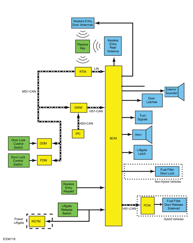
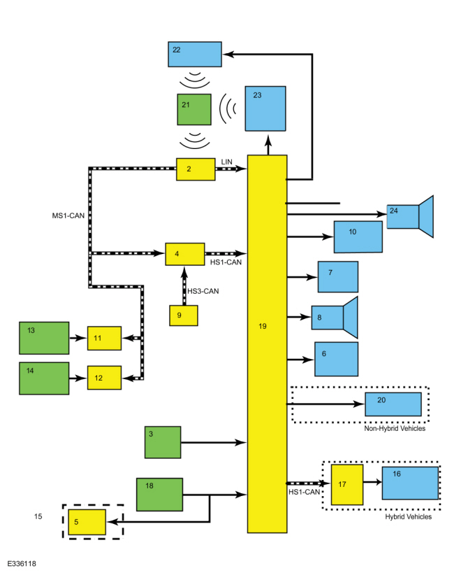
Refer to Wiring Diagrams Cell 42 for schematic and connector information. Normal Operation and Fault Conditions If DTC U0140:00 or U0422:00 is present with U300A:29, diagnose the lost communication DTC first. The ABS module, hydraulic pump and solenoid valves require an operating voltage between 10 and 17 volts. The parking brake system requires an operating voltage of 9 volts or higher. The ABS module receives this voltage from the BJB . The ABS module has 2 ground circuits. Excessive resistance or an open in one or more of these circuits, a discharged battery or a inoperative charging system results in the ABS module setting a DTC . DTC Fault Trigger Conditions
Possible Sources
Visual Inspection and Pre-checks
|
 Introduction
| Introduction
Normal Operation and Fault Conditions With the ignition ON, the HVAC control module sends messages to the GWM over the MS-CAN , The GWM relays these messages to the ABS module over the HS-CAN2 . If the ABS module does not receive these messages within the allotted time frame or if the messages contain invalid data, the module sets a DTC . This can be due to a HVAC control module failure, a circuit failure on the network or an excessive load on the network. For information on the messages sent to the ABS module by the HVAC control module, refer to the Network Message Chart in Section 206-09, Description and Operation in the Workshop Manual. DTC Fault Trigger Conditions
Possible Sources
|
| Introduction
NOTICE: Use the correct probe adapter(s) when making measurements. Failure to use the correct probe adapter(s) may cause damage to the connector. Refer to Wiring Diagrams Cell 42 for schematic and connector information. Normal Operation and Fault Conditions The brake booster vacuum sensor receives a sensor supply voltage of 5 volts from the ABS module. The sensor is also grounded through the ABS module. The sensor uses the pressure differential between the atmosphere and the brake booster vacuum chamber to produce a return voltage signal to the ABS module between 0.2 volt and 4.9 volts. The ABS module uses other sensor inputs such as wheel speed, brake pedal and stability sensors to determine if the vehicle is stopping and at what rate of deceleration. This information is compared against the vacuum pressure sensor to determine the validity of the sensor signal and the working condition of the sensor itself. DTC Fault Trigger Conditions
Possible Sources
Visual Inspection and Pre-checks
|
| Introduction
Normal Operation and Fault Conditions With the ignition ON, the BCM sends messages to the GWM over the HS-CAN1 . The GWM relays these message to the ABS module over the HS-CAN2 . If the ABS module does not receive these messages within the allotted time frame or if the messages contain invalid data, the module sets a DTC . This can be due to a BCM failure, a circuit failure on the network or an excessive load on the network. For information on the messages sent to the ABS module by the BCM , refer to the Network Message Chart in Section 206-09, Description and Operation in the Workshop Manual. DTC Fault Trigger Conditions
Possible Sources
|
|
Normal Operation and Fault Conditions
REFER to: Anti-Lock Brake System (ABS) and Stability Control - System
Operation and Component Description (206-09 Anti-Lock Brake System (ABS)
and Stability Control, Description and Operation). Possible Sources
|
||||
| E1 CHECK THE IPC (INSTRUMENT PANEL CLUSTER) FOR DIAGNOSTIC TROUBLE CODES (DTCS) | ||||
Are there any Diagnostic Trouble Codes (DTCs) present?
|
||||
| E2 CHECK THE PCM (POWERTRAIN CONTROL MODULE) FOR DIAGNOSTIC TROUBLE CODES (DTCS) | ||||
Are there any Diagnostic Trouble Codes (DTCs) present?
|
||||
| E3 CHECK THE RCM (RESTRAINTS CONTROL MODULE) FOR DIAGNOSTIC TROUBLE CODES (DTCS) | ||||
Are there any Diagnostic Trouble Codes (DTCs) present?
|
||||
| E4 CHECK THE ABS (ANTI-LOCK BRAKE SYSTEM) FOR MODULE DIAGNOSTIC TROUBLE CODES (DTCS) | ||||
Are there any Diagnostic Trouble Codes (DTCs) present?
|
| Introduction
Refer to Wiring Diagrams Cell 42 for schematic and connector information. Normal Operation and Fault Conditions The ABS module may set an over-voltage DTC if the vehicle has been recently jump started, the battery has been recently charged or the battery has been discharged. The battery may become discharged due to excessive load(s) on the charging system from aftermarket accessories or if the battery has been left unattended with the accessories on. The ABS module, hydraulic pump and solenoid valves require an operating voltage between 10 and 17 volts. The parking brake system requires an operating voltage of 9 volts or higher. The ABS module receives this voltage from the BJB . The ABS module has 2 ground circuits. DTC Fault Trigger Conditions
Possible Sources
|
| Introduction
Normal Operation and Fault Conditions The ABS module incorporates a function for testing the vehicle on a dynamometer to prevent wheel speed sensor Diagnostic Trouble Codes (DTCs) from setting during testing. The PCM sends a message to the ABS module when the vehicle is setup for testing. When the ABS module receives this message it knows to ignore discrepancies between the front and rear wheel speed sensors. The ABS module exits the test mode automatically when the PCM sends the exit message, the ignition is set to OFF, either of the non-driven wheels exceeds 20 km/h (12 mph) or a wheel speed sensor DTC is detected on any wheel speed sensor.
REFER to: Anti-Lock Brake System (ABS) and Stability Control - System
Operation and Component Description (206-09 Anti-Lock Brake System (ABS)
and Stability Control, Description and Operation). DTC Fault Trigger Conditions
Possible Sources
Visual Inspection and Pre-checks
|
| Introduction
NOTICE: Use the correct probe adapter(s) when making measurements. Failure to use the correct probe adapter(s) may cause damage to the connector. Refer to Wiring Diagrams Cell 42 for schematic and connector information. Normal Operation and Fault Conditions On vacuum brake booster equipped vehicles, The ABS module uses an internal solid state switch to operate the hydraulic pump motor. The ABS module tests the hydraulic pump motor by activating it for 30 milliseconds. The ABS module monitors the voltage drop across the hydraulic pump motor while the pump motor is being activated. After 30 milliseconds have passed, the ABS module stops applying voltage to the pump motor and monitors the voltage the spinning hydraulic pump motor is generating and the voltage drop across the hydraulic pump motor solid state switch. If the monitored voltages are not within the specifications, the ABS module sets one or more Diagnostic Trouble Codes (DTCs). On EBB equipped vehicles, the ABS module performs a check of the hydraulic system during start up and during drive cycles. The ABS module monitors the hydraulic pump motor in the EBB unit for any drops in voltage output during these tests. If a condition such as a short to ground or an open exist, the ABS module sets a DTC and modifies brake and ABS operation until the condition has been corrected. DTC Fault Trigger Conditions
Possible Sources
|
| Introduction
Normal Operation and Fault Conditions The EBB contains several hydraulic valves, hydraulic pressure sensors, a linear actuator and a pump motor. These components work in conjunction to provide the force necessary to bring the vehicle to a stop. The ABS module monitors these components for internal faults. If a fault occurs which impacts the base braking system, the ABS module sets one or more Diagnostic Trouble Codes (DTCs) and illuminates the red brake warning indicator. DTC Fault Trigger Conditions
Possible Sources
|
| Introduction
Normal Operation and Fault Conditions With the ignition ON, the GSM sends messages to the ABS module over the HS-CAN2 . If the ABS module does not receive these messages within the allotted time frame or if the messages contain invalid data, the module sets a DTC . This can be due to a GSM failure, a circuit failure on the network or an excessive load on the network. For information on the messages sent to the ABS module by the GSM , refer to the Network Message Chart in Section 206-09, Description and Operation in the Workshop Manual. DTC Fault Trigger Conditions
Possible Sources
|
| Introduction
Normal Operation and Fault Conditions The BCM is programmed with vehicle tire size information during the module configuration step. The BCM shares tire size information with other module over the HS-CAN1 through the GWM . When this DTC sets, the ABS module sends a message to the IPC to illuminate the ABS warning indicator. DTC Fault Trigger Conditions
Possible Sources
|
|
Normal Operation and Fault Conditions The brake fluid level switch is hardwired to the ABS module, the module monitors the switch and brake fluid level. If a circuit fault or fluid loss is detected, a DTC is set.
REFER to: Anti-Lock Brake System (ABS) and Stability Control - System
Operation and Component Description (206-09 Anti-Lock Brake System (ABS)
and Stability Control, Description and Operation). DTC Fault Trigger Conditions
Possible Sources
|
||||||||||||
| L1 CHECK THE ABS MODULE DIAGNOSTIC TROUBLE CODES (DTCS) | ||||||||||||
Is DTC C0049:01 present in the ABS module?
|
| Introduction
NOTICE: Use the correct probe adapter(s) when making measurements. Failure to use the correct probe adapter(s) may cause damage to the connector. Refer to Wiring Diagrams Cell 42 for schematic and connector information. Normal Operation and Fault Conditions Active wheel speed sensors generate a voltage signal proportional to wheel speed which is sent to the ABS module. Each wheel speed sensor is connected to the ABS module through 2 wires and a connector at each wheel speed sensor. The 2 circuits provide both sensor power and sensor signal return. When the ignition mode is set to ON, the ABS module carries out a self-test by sending a reference voltage through the wheel speed sensors and their circuitry. DTC Fault Trigger Conditions
Possible Sources
Visual Inspection and Pre-checks
|
| Introduction
NOTICE: Use the correct probe adapter(s) when making measurements. Failure to use the correct probe adapter(s) may cause damage to the connector. Refer to Wiring Diagrams Cell 42 for schematic and connector information. Normal Operation and Fault Conditions Active wheel speed sensors generate a voltage signal proportional to wheel speed which is sent to the ABS module. Each wheel speed sensor is connected to the ABS module through 2 wires and a connector at each wheel speed sensor. The 2 circuits provide both sensor power and sensor signal return. When the ignition mode is set to ON, the ABS module carries out a self-test by sending a reference voltage through the wheel speed sensors and their circuitry. DTC Fault Trigger Conditions
Possible Sources
Visual Inspection and Pre-checks
|
|
NOTE: If equipped, MyKey allows users to configure traction control to be either always on or selectable. If a MyKey restricted key is in use with the MyKey traction control feature configured to always on, traction control cannot be disabled. An admin key must be used to enable and disable traction control. NOTE: This test requires the use of at least 2 ignition keys (passive or IKT ) programmed to the vehicle; one admin ignition key and one restricted ignition key. Normal Operation and Fault Conditions The traction control switch is part of the instrument panel console switch assembly and is used to switch the traction control feature on or off. When the traction control switch is pressed, the instrument panel console switch assembly sends a ground signal to the IPC . The IPC sends a message to the GWM over the HS-CAN3 , the GWM relays this message to the ABS module over the HS-CAN2 . The ABS module continues to monitor for wheel spin but takes no action until the traction control message indicates the system has been turned on. DTC Fault Trigger Conditions
Possible Sources
NOTICE: Use the correct probe adapter(s) when making measurements. Failure to use the correct probe adapter(s) may cause damage to the connector. |
||||||||||
| O1 CHECK THE ABS MODULE FOR DTCS | ||||||||||
Is DTC C1109:64 or U0155:xx present in the ABS module?
|
||||||||||
| O2 CHECK THE IPC FOR DTCS | ||||||||||
Are there any Diagnostic Trouble Codes (DTCs) present in the IPC ?
|
||||||||||
| O3 VERIFY THE IGNITION KEY IN USE IS NOT RESTRICTED | ||||||||||
Does the message center display MYKEY ACTIVE DRIVE SAFELY?
|
||||||||||
| O4 VERIFY THE MYKEY TRACTION CONTROL SETTING | ||||||||||
Is the MyKey traction control setting configured to always on?
|
||||||||||
| O5 VERIFY TRACTION CONTROL FUNCTION CAN BE DISABLED USING THE ADMIN IGNITION KEY | ||||||||||
Can traction control be enabled and disabled using the admin ignition key?
|
||||||||||
| O6 CHECK THE INSTRUMENT PANEL CONSOLE SWITCH GROUND CIRCUIT FOR AN OPEN | ||||||||||
Is the resistance less than 3 ohms?
|
||||||||||
| O7 CHECK THE TRACTION CONTROL SIGNAL CIRCUIT FOR AN OPEN | ||||||||||
Is the resistance less than 3 ohms?
|
||||||||||
| O8 CHECK THE TRACTION CONTROL SIGNAL CIRCUIT FOR A SHORT TO GROUND | ||||||||||
Is the resistance greater than 10,000 ohms?
|
|
Normal Operation and Fault Conditions The ABS module and BCM share a secret code (target identifier) when the ignition is set to ON. This code is generated during the PATS programming procedure. If either a new BCM or a new ABS module has been installed, the PATS programming procedure must be carried out.
REFER to: Perimeter Anti-Theft Alarm - System Operation and Component
Description (419-01A Perimeter Anti-Theft Alarm, Description and
Operation). DTC Fault Trigger Conditions
Possible Sources
Visual Inspection and Pre-checks
|
||||||
| Diagnostic steps are not provided for this symptom or DTC. REFER to: Diagnostic Methods (100-00 General Information, Description and Operation). |
| Introduction
Normal Operation and Fault Conditions The PSCM calculates steering wheel rotation speed, angle and direction of rotation and sends the information to the ABS module over the HS-CAN2 . A failure of the HS-CAN2 , the PSCM or the internal sensors causes the ABS module to set one or more Diagnostic Trouble Codes (DTCs) and the ABS warning indicator is illuminated.
REFER to: Anti-Lock Brake System (ABS) and Stability Control - System
Operation and Component Description (206-09 Anti-Lock Brake System (ABS)
and Stability Control, Description and Operation). DTC Fault Trigger Conditions
Possible Sources
|
| Introduction
Normal Operation and Fault Conditions The CCM communicates with the IPMA over a private CAN . The IPMA sends the CCM messages to the ABS module over the HS-CAN2 . If the ABS module does not receive these messages within the allotted time frame or if the messages contain invalid data, the module sets a DTC . This can be due to a CCM failure, a circuit failure on the network or an excessive load on the network. For information on the messages sent to the ABS module by the CCM and IPMA , refer to the Network Message Chart in Section 206-09, Description and Operation in the Workshop Manual. DTC Fault Trigger Conditions
Possible Sources
|
| Introduction
Normal Operation and Fault Conditions With the ignition ON, the IPMA sends messages to the ABS module over the HS-CAN2 . If the ABS module does not receive these messages within the allotted time frame or if the messages contain invalid data, the module sets a DTC . This can be due to a IPMA failure, a circuit failure on the network or an excessive load on the network. For information on the messages sent to the ABS module by the IPMA , refer to the Network Message Chart in Section 206-09, Description and Operation in the Workshop Manual. DTC Fault Trigger Conditions
Possible Sources
|
|
Normal Operation and Fault Conditions These Diagnostic Trouble Codes (DTCs) are pre-set in a new ABS module and can only be cleared when the brake system has been successfully bled. The brake system requires a certain amount of hydraulic fluid for correct operation. When the brake system is filled, the ABS module sets a PID . If the vehicle is operated and the ABS module detects this PID has not been set, a DTC is set. DTC Fault Trigger Conditions
Possible Sources
|
|||||||||
| T1 CHECK THE ABS (ANTI-LOCK BRAKE SYSTEM)DIAGNOSTIC TROUBLE CODES (DTCS) | |||||||||
Is any DTC from the DTC Fault Trigger Conditions table present?
|
|
Normal Operation and Fault Conditions The hill descent control switch is part of the instrument panel console switch assembly and is hardwired to the IPC . When the hill descent control switch is pressed, the IPC receives a ground signal and sends a message to the GWM over the MS-CAN . The GWM relays the message to the ABS module over the HS-CAN2 . If the ABS module does not receive any messages within a certain time frame (usually less than 1 second) or if the message contains invalid information, the ABS module sets a DTC . Possible Sources
|
||||||||||
| U1 CHECK THE IPC COMMUNICATIONS | ||||||||||
Does the IPC communicate with the diagnostic scan tool?
|
||||||||||
| U2 CHECK THE IPC DIAGNOSTIC TROUBLE CODES (DTCS) | ||||||||||
Are there any Diagnostic Trouble Codes (DTCs) present and active in the IPC ?
|
||||||||||
| U3 CHECK THE INSTRUMENT PANEL CONSOLE SWITCH GROUND CIRCUIT FOR AN OPEN | ||||||||||
Is the resistance less than 3 ohms?
|
||||||||||
| U4 CHECK THE HILL DESCENT CONTROL CIRCUIT FOR A SHORT TO VOLTAGE | ||||||||||
Is any voltage present?
|
||||||||||
| U5 CHECK THE HILL DESCENT CONTROL CIRCUIT FOR A SHORT TO GROUND | ||||||||||
Is the resistance greater than 10,000 ohms?
|
||||||||||
| U6 CHECK THE HILL DESCENT CONTROL CIRCUIT FOR AN OPEN CIRCUIT | ||||||||||
Is the resistance less than 3 ohms?
|
|
Normal Operation and Fault Conditions The ABS module monitors all base brake, anti-lock brake, traction control and stability control functions and features. If a system error occurs which could cause irreparable damage to the system, the ABS module disables the EBB unit. The base brake system still functions, but there is no brake boost assist. This can also occur if the EBB unit loses power or ground. System over-voltage combined with other specific circumstances may cause the EBB unit to provide excessive brake assist or a "touchy" pedal, where the brakes apply heavily with a light application of the brake pedal. In either of these cases, no brake assist or too much brake assist, the ABS module sets Diagnostic Trouble Codes (DTCs) indicating possible concerns. Possible Sources
Visual Inspection and Pre-checks
|
| Diagnostic steps are not provided for this symptom or DTC. REFER to: Diagnostic Methods (100-00 General Information, Description and Operation). |
| Introduction
Normal Operation and Fault Conditions The ABS module uses several sensors (wheel speed, steering wheel rotation, stability control) to determine if ABS or stability control intervention is required. Accurate sensor readings rely on the vehicle being in good operational condition with as few mechanical and electrical concerns as possible. In addition, the wheels and tires must be within vehicle manufacturer's specifications as described on the VC label and the base brake system and parking brake system must be in good operational condition. If one or more of these items or systems are in need or repair or are not working at full capacity, the ABS or stability control system may activate when the driving condition does not warrant activation. Possible Sources
|
|
Normal Operation and Fault Conditions The ABS module continually monitors the brake system for potential system concerns. During module wake up, several items are monitored and certain operations are expected to be performed. If one or more of these do not occur as expected, the ABS module sets a DTC and requests the illumination of the ABS warning indicator.
REFER to: Anti-Lock Brake System (ABS) and Stability Control - System
Operation and Component Description (206-09 Anti-Lock Brake System (ABS)
and Stability Control, Description and Operation). DTC Fault Trigger Conditions
Possible Sources
|
||||||
| Diagnostic steps are not provided for this symptom or DTC. REFER to: Diagnostic Methods (100-00 General Information, Description and Operation). |
| Introduction
Normal Operation and Fault Conditions The ABS module carries out self tests during operation, the module also monitors various inputs and compares the values to what is expected. If the values received are out of range, are not what is expected, or if any of the self tests fail, the ABS module sets a DTC . DTC Fault Trigger Conditions
Possible Sources
|
| Introduction
Normal Operation and Fault Conditions During new module installation, configuration files are loaded into the new module being replaced. If a discrepancy is detected between the modules or an incomplete programming procedure is carried out, a DTC is set. DTC Fault Trigger Conditions
Possible Sources
|
|
Normal Operation and Fault Conditions The selectable drive mode switch is part of the instrument panel console switch assembly and is hardwired to the HVAC control module. When the drive mode switch is pressed, the HVAC control module receives a ground signal and sends a message to the GWM over the MS-CAN . The GWM relays the message to the ABS module over the HS-CAN2 . If the ABS module does not receive any messages within a certain time frame (usually less than 1 second) or if the message contains invalid information, the ABS module sets a DTC . DTC Fault Trigger Conditions
Possible Sources
|
||||||||||
| AA1 CHECK THE HVAC CONTROL MODULE COMMUNICATIONS | ||||||||||
Does the HVAC control module communicate with the diagnostic scan tool?
|
||||||||||
| AA2 CHECK THE HVAC (HEATING, VENTILATION AND AIR CONDITIONING) CONTROL MODULE DIAGNOSTIC TROUBLE CODES (DTCS) | ||||||||||
Are there any Diagnostic Trouble Codes (DTCs) present and active in the HVAC control module?
|
||||||||||
| AA3 CHECK THE INSTRUMENT PANEL CONSOLE SWITCH GROUND CIRCUIT FOR AN OPEN | ||||||||||
Is the resistance less than 3 ohms?
|
||||||||||
| AA4 CHECK THE SELECTABLE DRIVE MODE CIRCUIT FOR A SHORT TO VOLTAGE | ||||||||||
Is any voltage present?
|
||||||||||
| AA5 CHECK THE SELECTABLE DRIVE MODE CIRCUIT FOR A SHORT TO GROUND | ||||||||||
Is the resistance greater than 10,000 ohms?
|
||||||||||
| AA6 CHECK THE SELECTABLE DRIVE MODE CIRCUIT FOR AN OPEN CIRCUIT | ||||||||||
Is the resistance less than 3 ohms?
|
| Introduction
NOTICE: Use the correct probe adapter(s) when making measurements. Failure to use the correct probe adapter(s) may cause damage to the connector. Refer to Wiring Diagrams Cell 42 for schematic and connector information. Normal Operation and Fault Conditions The wheel speed sensor uses the tone ring to generate a square wave signal proportional to wheel speed which is sent to the ABS module. The front wheel bearing, rear axle shafts, tone rings and wheel speed sensors must be undamaged and free from any contamination to produce a clean signal for use by the ABS module. Also, all 4 tires and wheels must be of the same manufacturer recommended size for the wheel speed sensor to generate an accurate wheel speed signal. DTC Fault Trigger Conditions
Possible Sources
|
| Introduction
Normal Operation and Fault Conditions The BPP switch is also known as the stoplamp switch. The ABS module receives BPP switch input from the PCM through the GWM over the HS-CAN . The ABS module compares this information against brake fluid pressure sensor input and brake pedal input to determine if the BPP switch input is valid. An incorrectly installed BPP switch can cause a signal plausibility concern. An implausible signal can also be created if a driver is resting one foot on the brake pedal while using the other foot to press the accelerator.
REFER to: Anti-Lock Brake System (ABS) and Stability Control - System
Operation and Component Description (206-09 Anti-Lock Brake System (ABS)
and Stability Control, Description and Operation). DTC Fault Trigger Conditions
Possible Sources
|
| Introduction
Normal Operation and Fault Conditions The ABS module uses information from the wheel speed sensors, RCM and PSCM to determine when stability control intervention is necessary to help stabilize the vehicle. The ABS module uses the EBB unit (electric boosted vehicles) or the HCU (vacuum boosted vehicles) to modulate the brake fluid pressure to the brake calipers and continues to monitor the sensor and module input until the instability event has been corrected. Once the sensors and modules indicate the instability event has been corrected, the ABS module deactivates the EBB unit (electric boosted vehicles) or the HCU (vacuum boosted vehicles). Under inflated tires, wheels and tires that do not match VC label specifications, suspension and steering damage, and one or more sensor failures contribute to the ABS module setting this DTC . DTC Fault Trigger Conditions
Possible Sources
|
| Introduction
Normal Operation and Fault Conditions With the ignition ON, the PSCM sends messages to the ABS module over the HS-CAN2 . If the ABS module does not receive these messages within the allotted time frame or if the messages contain invalid data, the module sets a DTC . This can be due to a PSCM failure, a circuit failure on the network or an excessive load on the network. For information on the messages sent to the ABS module by the PSCM , refer to the Network Message Chart in Section 206-09, Description and Operation in the Workshop Manual. DTC Fault Trigger Conditions
Possible Sources
|
| Introduction
Normal Operation and Fault Conditions When the ignition is set to ON, the ABS module and the BCM share VIN information through the GWM over the HS-CAN1 and FD-CAN . When a new EBB unit or ABS module is installed, the ABS module must
be programmed with the vehicle information. REFER to: Module
Configuration - System Operation and Component Description (418-01
Module Configuration, Description and Operation). DTC Fault Trigger Conditions
Possible Sources
|
|
Normal Operation and Fault Conditions With the ignition ON, the diagnostic scan tool communicates with the ABS module over the HS-CAN2 . Communications can be interrupted by a wiring condition such as a short to ground, a short to voltage or an open circuit; module failure may also be a cause of no communication. Refer to Section 418-00 to diagnose the no communication concern.
REFER to: Communications Network (418-00 Module Communications Network,
Diagnosis and Testing). Possible Sources
|
| Diagnostic steps are not provided for this symptom or DTC. REFER to: Diagnostic Methods (100-00 General Information, Description and Operation). |
| Introduction
Normal Operation and Fault Conditions The ABS module uses a vacuum sensor to monitor the brake booster vacuum. On 2.0L EcoBoost engines, a camshaft driven vacuum pump supplies the vacuum to the brake booster. The vacuum pump is expected to produce at least 600 mBar (18 In-Hg). A leak in a vacuum hose, brake booster or one of the seals on the brake booster or vacuum pump prevents the vacuum pump from achieving the required amount of vacuum. Damage or an internal failure also prevents the vacuum pump from operating at peak capacity. On all other engines, the engine supplies the vacuum to the brake booster through a series of hoses and tubes. A leak in a vacuum hose, tube, brake booster or one of the seals on the brake booster or vacuum pump prevents the brake booster from achieving the required amount of vacuum. DTC Fault Trigger Conditions
Possible Sources
|
| Introduction
Normal Operation and Fault Conditions With the ignition ON, the PCM sends messages to the GWM over the HS-CAN1 . The GWM relays these message to the ABS module over the HS-CAN2 . If the ABS module does not receive these messages within the allotted time frame or if the messages contain invalid data, the module sets a DTC . This can be due to a PCM failure, a circuit failure on the network or an excessive load on the network. For information on the messages sent to the ABS module by the PCM , refer to the Network Message Chart in Section 206-09, Description and Operation in the Workshop Manual. The TCM is an internal component of the PCM . DTC Fault Trigger Conditions
Possible Sources
|
|
Normal Operation and Fault Conditions With the ignition in RUN, the ABS module continuously monitors the base brake system, the ABS , and the stability control system. If there is a concern present in one of the systems, the ABS module sets a DTC and sends a message to the GWM over the FD-CAN , the GWM relays this message to the IPC . Once the message is received, the IPC illuminates the appropriate warning indicator. The IPC also illuminates the warning indicators as part of a self
test when the ignition is set to RUN or ACC. REFER to: Instrument Panel
Cluster (IPC) - System Operation and Component Description (413-01
Instrumentation, Message Center and Warning Chimes, Description and
Operation). Possible Sources
Visual Inspection and Pre-checks
|
| Diagnostic steps are not provided for this symptom or DTC. REFER to: Diagnostic Methods (100-00 General Information, Description and Operation). |
| Introduction
Normal Operation and Fault Conditions With the ignition ON, the GWM sends messages to the ABS module over the HS-CAN2 . If the ABS module does not receive these messages within the allotted time frame or if the messages contain invalid data, the module sets a DTC . This can be due to a GWM failure, a circuit failure on the network or an excessive load on the network. For information on the messages sent to the ABS module by the GWM , refer to the Network Message Chart in Section 206-09, Description and Operation in the Workshop Manual. DTC Fault Trigger Conditions
Possible Sources
|
| Introduction
Normal Operation and Fault Conditions The ABS module carries out a self-check each time the ignition mode
is changed to RUN. If the ABS module detects a fault, one or more
Diagnostic Trouble Codes (DTCs) set. REFER to: Anti-Lock Brake System
(ABS) and Stability Control - System Operation and Component Description
(206-09 Anti-Lock Brake System (ABS) and Stability Control, Description
and Operation). DTC Fault Trigger Conditions
Possible Sources
|
| Introduction
Normal Operation and Fault Conditions The ABS module monitors various inputs and compares the values to what should be expected. If the values received are out of range or not what should be expected, the ABS module sets a DTC . DTC Fault Trigger Conditions
Possible Sources
|
| Introduction
Normal Operation and Fault Conditions The ABS module monitors various inputs and compares the values to what should be expected. If the values received are out of range or not what is expected, the ABS module sets a DTC . When a new ABS module or RCM is installed, the stability control sensors in the RCM must be initialized. This is accomplished using a diagnostic scan tool to run the ABS Calibration routine. DTC Fault Trigger Conditions
Possible Sources
|
|
Normal Operation and Fault Conditions Vehicles equipped with EPB are also equipped with an auto hold feature. This feature must be enabled by the driver by pressing the auto hold switch once the driver seatbelt is buckled and the driver door is closed. The auto hold switch is part of the instrument panel console switch assembly and is hardwired to the HVAC control module. Pressing the auto hold switch enables the auto hold feature, but does not activate auto hold. When the switch is pressed, the HVAC control module receives a ground signal from the switch. The HVAC control module sends a message to the GWM over the MS-CAN . The GWM relays the message to the ABS module over the HS-CAN2 indicating the system has been enabled. The ABS module then waits for messages from the RCM and BCM as well as ABS sensor information to indicate the auto hold feature can be activated. Once all criteria has been met, the ABS module activates the auto hold feature. In the case of a system error, the instrument cluster displays messages and icons. Possible Sources
|
||||||||||
| AO1 CHECK THE NETWORK COMMUNICATIONS | ||||||||||
Do the HVAC control module, RCM and BCM communicate with the diagnostic scan tool?
|
||||||||||
| AO2 CHECK FOR ACTIVE DIAGNOSTIC TROUBLE CODES (DTCS) | ||||||||||
Are there any Diagnostic Trouble Codes (DTCs) present and active in the HVAC control module, RCM or BCM ?
|
||||||||||
| AO3 CHECK THE AUTO HOLD ENGAGE CIRCUIT FOR A SHORT TO VOLTAGE | ||||||||||
Is any voltage present?
|
||||||||||
| AO4 CHECK THE AUTO HOLD ENGAGE CIRCUIT FOR A SHORT TO GROUND | ||||||||||
Is the resistance greater than 10,000 ohms?
|
||||||||||
| AO5 CHECK THE AUTO HOLD ENGAGE CIRCUIT FOR AN OPEN CIRCUIT | ||||||||||
Is the resistance less than 3 ohms?
|
| Introduction
Normal Operation and Fault Conditions With the ignition ON, the AWD module sends messages to the GWM over the HS-CAN1 . The GWM relays these message to the ABS module over the HS-CAN2 . If the ABS module does not receive these messages within the allotted time frame or if the messages contain invalid data, the module sets a DTC . This can be due to a AWD module failure, a circuit failure on the network or an excessive load on the network. For information on the messages sent to the ABS module by the AWD module refer to the Network Message Chart in Section 206-09, Description and Operation in the Workshop Manual. DTC Fault Trigger Conditions
Possible Sources
|
| Introduction
Normal Operation and Fault Conditions The CCM communicates with the IPMA over a private CAN . The IPMA sends the CCM messages to the GWM over the HS-CAN2 . The GWM relays these messages to the ABS module over the FD-CAN . If the ABS module does not receive these messages within the allotted time frame or if the messages contain invalid data, the module sets a DTC . This can be due to a CCM failure, a circuit failure on the network or an excessive load on the network. For information on the messages sent to the ABS module by the CCM and IPMA , refer to the Network Message Chart in Section 206-09, Description and Operation in the Workshop Manual. DTC Fault Trigger Conditions
Possible Sources
|
| Introduction
Normal Operation and Fault Conditions With the ignition ON, the IPC sends messages to the GWM over the HS-CAN3 . The GWM relays these messages to the ABS module over the HS-CAN2 . If the ABS module does not receive these messages within the allotted time frame or if the messages contain invalid data, the module sets a DTC . This can be due to a IPC failure, a circuit failure on the network or an excessive load on the network. For information on the messages sent to the ABS module by the IPC , refer to the Network Message Chart in Section 206-09, Description and Operation in the Workshop Manual. DTC Fault Trigger Conditions
Possible Sources
|
| Introduction
Normal Operation and Fault Conditions With the ignition ON, the FCIM sends messages to the GWM over the MS-CAN , The GWM relays these messages to the ABS module over the HS-CAN2 . If the ABS module does not receive these messages within the allotted time frame or if the messages contain invalid data, the module sets a DTC . This can be due to a FCIM failure, a circuit failure on the network or an excessive load on the network. For information on the messages sent to the ABS module by the FCIM , refer to the Network Message Chart in Section 206-09, Description and Operation in the Workshop Manual. The hill descent control switch is part of the FCIM . When the hill descent control switch is touched, the FCIM sends a message to the GWM over the HS-CAN3 . The GWM relays the message to the ABS module over the HS-CAN2 . If the ABS module does not receive these messages within a certain time frame (usually less than 1 second) or if the message contains invalid information, the ABS module sets a DTC . DTC Fault Trigger Conditions
Possible Sources
|
| Introduction
NOTICE: Use the correct probe adapter(s) when making measurements. Failure to use the correct probe adapter(s) may cause damage to the connector. Refer to Wiring Diagrams Cell 42 for schematic and connector information. Normal Operation and Fault Conditions The EBB unit uses a motor to pressurize the brake system and to operate the ABS , ESC , RSC and other stability control features. The ABS module monitors the motor performance and sets a DTC when a motor fault is detected. DTC Fault Trigger Conditions
Possible Sources
|
| Introduction
NOTE: The HEV - PCM may also be known as the SOBDMC . Normal Operation and Fault Conditions With the ignition ON, the HEV - PCM sends messages to the GWM over the HS-CAN1 . The GWM relays these message to the ABS module over the HS-CAN2 . If the ABS module does not receive these messages within the allotted time frame or if the messages contain invalid data, the module sets a DTC . This can be due to a HEV - PCM failure, a circuit failure on the network or an excessive load on the network. For information on the messages sent to the ABS module by the HEV - PCM , refer to the Network Message Chart in Section 206-09, Description and Operation in the Workshop Manual. DTC Fault Trigger Conditions
Possible Sources
|
| Introduction
Normal Operation and Fault Conditions The ABS module receives vehicle yaw rate, lateral acceleration, longitudinal acceleration and roll rate from RCM over the HS-CAN2 , through the GWM . The yaw rate sensor, lateral accelerometer, longitudinal accelerometer and roll rate sensor are all contained in the RCM . A failure of the HS-CAN2 , an internal failure of the RCM or the internal sensors causes the ABS module to set one or more Diagnostic Trouble Codes (DTCs). DTC Fault Trigger Conditions
Possible Sources
|

 Removal and Installation - Anti-Lock Brake System (ABS) Module - Vehicles With: Vacuum Brake Booster
Removal
NOTE:
A new HCU is equipped with an ABS module. A new ABS module does not come equipped with an HCU .
NOTE:
Removal steps in this procedure may contain installation details...
Other information:
Ford Escape 2020-2026 Service Manual: General Procedures - Air Conditioning (A/C) System Recovery, Evacuation and Charging
Recovery NOTICE: Use an A/C refrigerant analyzer before recovering any of the vehicle's A/C refrigerant. Failure to do so puts the shop's bulk refrigerant at risk of contamination. If the vehicle's A/C refrigerant is contaminated, refer the customer to the service facility that carried out the last A/C service...
Ford Escape 2020-2026 Service Manual: General Procedures - High Voltage Battery Leak Test - Plug-In Hybrid Electric Vehicle (PHEV)
Special Tool(s) / General Equipment 414-010Leak Test Adapter 414-011Leak Test Adapter 414-012Leak Test Adapter 414-013Leak Test Adapter 414-014Leak Test Adapter 414-015Leak Test Adapter 414-022Adapter, Leak Test Leak detection NOTE: This test is meant to be a secondary check after a service procedure is performed on the high voltage batt..
Categories
- Manuals Home
- 4th Generation Ford Escape Owners Manual
- 4th Generation Ford Escape Service Manual
- Drive Modes
- Child Safety Locks
- What Is the Tire Pressure Monitoring System. Tire Pressure Monitoring System Overview
- New on site
- Most important about car
Fastening the Seatbelts
