Ford Escape: Four-Wheel Drive Systems / Diagnosis and Testing - Four-Wheel Drive Systems
Diagnostic Trouble Code (DTC) Chart
Diagnostics in this manual assume a certain skill level and knowledge of Ford-specific diagnostic practices.
REFER to: Diagnostic Methods (100-00 General Information, Description and Operation).
| Module | DTC | Description | Action |
|---|---|---|---|
| AWD | C0090:16 | 4WD/AWD Power Transfer Unit Actuator: Circuit Voltage Below Threshold | GO to Pinpoint Test A |
| AWD | C0090:18 | 4WD/AWD Power Transfer Unit Actuator: Circuit Current Below Threshold | GO to Pinpoint Test A |
| AWD | C0090:19 | 4WD/AWD Power Transfer Unit Actuator: Circuit Current Above Threshold | GO to Pinpoint Test A |
| AWD | C0090:71 | 4WD/AWD Power Transfer Unit Actuator: Actuator Stuck | GO to Pinpoint Test A |
| AWD | C0091:17 | 4WD/AWD Power Transfer Unit Position Sensor 'A': Circuit Voltage Above Threshold | GO to Pinpoint Test B |
| AWD | C0091:32 | 4WD/AWD Power Transfer Unit Position Sensor 'A': Signal Low Time Less Than Minimum | GO to Pinpoint Test B |
| AWD | C0091:33 | 4WD/AWD Power Transfer Unit Position Sensor 'A': Signal Low Time Greater Than Maximum | GO to Pinpoint Test B |
| AWD | C0091:38 | 4WD/AWD Power Transfer Unit Position Sensor 'A': Signal Frequency Incorrect | GO to Pinpoint Test B |
| AWD | C0091:92 | 4WD/AWD Power Transfer Unit Position Sensor 'A': Performance Or Incorrect Operation | GO to Pinpoint Test B |
| AWD | C0092:17 | 4WD/AWD Power Transfer Unit Position Sensor 'B': Circuit Voltage Above Threshold | GO to Pinpoint Test C |
| AWD | C0092:32 | 4WD/AWD Power Transfer Unit Position Sensor 'B': Signal Low Time Less Than Minimum | GO to Pinpoint Test C |
| AWD | C0092:33 | 4WD/AWD Power Transfer Unit Position Sensor 'B': Signal Low Time Greater Than Maximum | GO to Pinpoint Test C |
| AWD | C0092:38 | 4WD/AWD Power Transfer Unit Position Sensor 'B': Signal Frequency Incorrect | GO to Pinpoint Test C |
| AWD | C0092:92 | 4WD/AWD Power Transfer Unit Position Sensor 'B': Performance Or Incorrect Operation | GO to Pinpoint Test M |
| AWD | C0093:16 | 4WD/AWD Power Transfer Unit Temperature Sensor: Circuit Voltage Below Threshold | GO to Pinpoint Test D |
| AWD | C0093:17 | 4WD/AWD Power Transfer Unit Temperature Sensor: Circuit Voltage Above Threshold | GO to Pinpoint Test D |
| AWD | C0093:92 | 4WD/AWD Power Transfer Unit Temperature Sensor: Performance Or Incorrect Operation | GO to Pinpoint Test D |
| AWD | C0095:07 | 4WD/AWD Rear Differential Unit Actuator 'A': Mechanical Failures | GO to Pinpoint Test I |
| AWD | C0095:18 | 4WD/AWD Rear Differential Unit Actuator 'A': Circuit Current Below Threshold | GO to Pinpoint Test I |
| AWD | C0095:19 | 4WD/AWD Rear Differential Unit Actuator 'A': Circuit Current Above Threshold | GO to Pinpoint Test I |
| AWD | C0095:44 | 4WD/AWD Rear Differential Unit Actuator 'A': Data Memory Failure | GO to Pinpoint Test N |
| AWD | C0095:71 | 4WD/AWD Rear Differential Unit Actuator 'A': Actuator Stuck | GO to Pinpoint Test I |
| AWD | C0095:92 | 4WD/AWD Rear Differential Unit Actuator 'A': Performance Or Incorrect Operation | GO to Pinpoint Test I |
| AWD | C0095:99 | 4WD/AWD Rear Differential Unit Actuator 'A': Exceeded Learning Limit | GO to Pinpoint Test I |
| AWD | C0096:54 | 4WD/AWD Rear Differential Unit Actuator 'A' Data: Missing Calibration | GO to Pinpoint Test N |
| AWD | C0099:14 | 4WD/AWD Rear Differential Unit Actuator 'A' Position Sensor 'A': Circuit Short To Ground Or Open | GO to Pinpoint Test G |
| AWD | C0099:16 | 4WD/AWD Rear Differential Unit Actuator 'A' Position Sensor 'A': Circuit Voltage Below Threshold | GO to Pinpoint Test G |
| AWD | C0099:17 | 4WD/AWD Rear Differential Unit Actuator 'A' Position Sensor 'A': Circuit Voltage Above Threshold | GO to Pinpoint Test G |
| AWD | C009A:14 | 4WD/AWD Rear Differential Unit Actuator 'A' Position Sensor 'B': Circuit Short To Ground Or Open | GO to Pinpoint Test G |
| AWD | C009A:16 | 4WD/AWD Rear Differential Unit Actuator 'A' Position Sensor 'B': Circuit Voltage Below Threshold | GO to Pinpoint Test G |
| AWD | C009A:17 | 4WD/AWD Rear Differential Unit Actuator 'A' Position Sensor 'B': Circuit Voltage Above Threshold | GO to Pinpoint Test G |
| AWD | C009B:14 | 4WD/AWD Rear Differential Unit Actuator 'A' Position Sensor 'C': Circuit Short To Ground Or Open | GO to Pinpoint Test G |
| AWD | C009B:16 | 4WD/AWD Rear Differential Unit Actuator 'A' Position Sensor 'C': Circuit Voltage Below Threshold | GO to Pinpoint Test G |
| AWD | C009B:17 | 4WD/AWD Rear Differential Unit Actuator 'A' Position Sensor 'C': Circuit Voltage Above Threshold | GO to Pinpoint Test G |
| AWD | C009C:00 | 4WD/AWD Rear Differential Unit Actuator 'A' Position Sensor Correlation: No Sub Type Information | GO to Pinpoint Test G |
| AWD | C00A1:08 | Driveline Control Module: Bus Signal/Message Failures | GO to Pinpoint Test E |
| AWD | C00A1:46 | Driveline Control Module: Calibration/Parameter Memory Failure | GO to Pinpoint Test E |
| AWD | C00A1:57 | Driveline Control Module: Invalid/Incompatible Software Component | GO to Pinpoint Test E |
| AWD | C00A1:F1 | Driveline Control Module: Ethernet 2 Failure | GO to Pinpoint Test E |
| AWD | C00A2:01 | Driveline Control Module Power Transfer Unit Control Circuit Driver: General Electrical Failure | GO to Pinpoint Test E |
| AWD | C00A2:19 | Driveline Control Module Power Transfer Unit Control Circuit Driver: Circuit Current Above Threshold | GO to Pinpoint Test A |
| AWD | C00A2:1C | Driveline Control Module Power Transfer Unit Control Circuit Driver: Circuit Voltage Out Of Range | GO to Pinpoint Test B |
| AWD | C00A2:49 | Driveline Control Module Power Transfer Unit Control Circuit Driver: Internal Electronic Failure | GO to Pinpoint Test E |
| AWD | C00A2:4B | Driveline Control Module Power Transfer Unit Control Circuit Driver: Over Temperature | GO to Pinpoint Test E |
| AWD | C00A2:96 | Driveline Control Module Power Transfer Unit Control Circuit Driver: Component Internal Failure | GO to Pinpoint Test E |
| AWD | C00A3:01 | Driveline Control Module Rear Differential Unit 'A' Control Circuit Driver: General Electrical Failure | GO to Pinpoint Test E |
| AWD | C00A3:1C | Driveline Control Module Rear Differential Unit 'A' Control Circuit Driver: Circuit Voltage Out Of Range | GO to Pinpoint Test J |
| AWD | C00A3:49 | Driveline Control Module Rear Differential Unit 'A' Control Circuit Driver: Internal Electronic Failure | GO to Pinpoint Test E |
| AWD | C00A3:4B | Driveline Control Module Rear Differential Unit 'A' Control Circuit Driver: Over Temperature | GO to Pinpoint Test E |
| AWD | C00A3:96 | Driveline Control Module Rear Differential Unit 'A' Control Circuit Driver: Component Internal Failure | GO to Pinpoint Test E |
| AWD | C05D9:74 | 4WD/AWD Clutch 'A' Actuator Control Circuit Performance: Actuator Slipping | GO to Pinpoint Test I |
| AWD | C05F0:00 | Rear Drive Shaft Speed Sensor Circuit Low: No Sub Type Information | GO to Pinpoint Test H |
| AWD | C05F1:00 | Rear Drive Shaft Speed Sensor Circuit High: No Sub Type Information | GO to Pinpoint Test H |
| AWD | C05F3:00 | Rear Drive Shaft Speed Sensor Circuit: No Sub Type Information | GO to Pinpoint Test H |
| AWD | C05F4:00 | Rear Drive Shaft Speed Sensor Circuit Range/Performance: No Sub Type Information | GO to Pinpoint Test H |
| AWD | P0562:00 | System Voltage Low: No Sub Type Information | GO to Pinpoint Test E |
| AWD | P0563:00 | System Voltage High: No Sub Type Information | GO to Pinpoint Test E |
| AWD | P0603:00 | Internal Control Module Keep Alive Memory (KAM) Error: No Sub Type Information | GO to Pinpoint Test E |
| AWD | P0604:00 | Internal Control Module Random Access Memory (RAM) Error: No Sub Type Information | GO to Pinpoint Test E |
| AWD | P0605:00 | Internal Control Module Read Only Memory (ROM) Error: No Sub Type Information | GO to Pinpoint Test E |
| AWD | P0607:00 | Control Module Performance: No Sub Type Information | GO to Pinpoint Test E |
| AWD | P060A:00 | Internal Control Module Monitoring Processor Performance: No Sub Type Information | GO to Pinpoint Test E |
| AWD | P060B:00 | Internal Control Module A/D Processing Performance: No Sub Type Information | GO to Pinpoint Test E |
| AWD | P060C:00 | Internal Control Module Main Processor Performance: No Sub Type Information | GO to Pinpoint Test E |
| AWD | P0630:00 | VIN Not Programmed or Incompatible - ECM/PCM: No Sub Type Information | GO to Pinpoint Test K |
| AWD | P064F:00 | Unauthorized Software/Calibration Detected: No Sub Type Information | GO to Pinpoint Test E |
| AWD | P068A:00 | ECM/PCM Power Relay De-Energized - Too Early: No Sub Type Information | GO to Pinpoint Test E |
| AWD | P1001:00 | KOER Not Able to Complete, KOER Aborted: No Sub Type Information | GO to Pinpoint Test L |
| AWD | P1397:00 | System Voltage Out Of Self Test Range: No Sub Type Information | GO to Pinpoint Test L |
| AWD | P1501:00 | Vehicle Speed Sensor Out Of Self Test Range: No Sub Type Information | GO to Pinpoint Test L |
| AWD | P160A:00 | Control Module Vehicle Options Reconfiguration Error: No Sub Type Information | GO to Pinpoint Test K |
| AWD | P1674:00 | Control Module Software Corrupted: No Sub Type Information | GO to Pinpoint Test E |
| AWD | P1705:00 | Transmission Range Circuit Not Indicating Park/Neutral During Self Test: No Sub Type Information | GO to Pinpoint Test L |
| AWD | U0100:00 | Lost Communication With ECM/PCM 'A': No Sub Type Information | GO to Pinpoint Test F |
| AWD | U0101:00 | Lost Communication with TCM: No Sub Type Information | GO to Pinpoint Test F |
| AWD | U0121:00 | Lost Communication With Anti-Lock Brake System (ABS) Control Module 'A': No Sub Type Information | GO to Pinpoint Test F |
| AWD | U0126:00 | Lost Communication With Steering Angle Sensor Module: No Sub Type Information | GO to Pinpoint Test F |
| AWD | U0137:00 | Lost Communication With Trailer Brake Control Module: No Sub Type Information | GO to Pinpoint Test F |
| AWD | U0138:00 | Lost Communication with All Terrain Control Module: No Sub Type Information | GO to Pinpoint Test F |
| AWD | U0140:00 | Lost Communication With Body Control Module: No Sub Type Information | GO to Pinpoint Test F |
| AWD | U0146:00 | Lost Communication With Serial Data Gateway 'A': No Sub Type Information | GO to Pinpoint Test F |
| AWD | U0155:00 | Lost Communication With Instrument Panel Cluster (IPC) Control Module: No Sub Type Information | GO to Pinpoint Test F |
| AWD | U0212:00 | Lost Communication With Steering Column Control Module: No Sub Type Information | GO to Pinpoint Test F |
| AWD | U0401:00 | Invalid Data Received from ECM/PCM A: No Sub Type Information | GO to Pinpoint Test O |
| AWD | U0402:00 | Invalid Data Received from TCM: No Sub Type Information | GO to Pinpoint Test O |
| AWD | U0415:00 | Invalid Data Received from Anti-Lock Brake System (ABS) Control Module 'A': No Sub Type Information | GO to Pinpoint Test O |
| AWD | U0422:00 | Invalid Data Received From Body Control Module: No Sub Type Information | GO to Pinpoint Test O |
| AWD | U0423:00 | Invalid Data Received from Instrument Panel Cluster Control Module: No Sub Type Information | GO to Pinpoint Test O |
| AWD | U0428:00 | Invalid Data Received From Steering Angle Sensor Module: No Sub Type Information | GO to Pinpoint Test O |
| AWD | U2100:00 | Initial Configuration Not Complete: No Sub Type Information | GO to Pinpoint Test K |
| AWD | U2101:00 | Control Module Configuration Incompatible: No Sub Type Information | GO to Pinpoint Test K |
| AWD | U2200:00 | Control Module Configuration Memory Corrupt: No Sub Type Information | GO to Pinpoint Test E |
Pinpoint Tests
|
Refer to Wiring Diagrams Cell 34 for schematic and connector information. Normal Operation and Fault Conditions The PTU actuator motor consists of a reversible DC motor, a reduction gear set, an actuating cam, a shift fork, and a pair of position sensors. The AWD module switches power and ground to the PTUMC+ and PTUMC- circuits to connect or disconnect the PTU. DTC Fault Trigger Conditions
Possible Sources
|
||||||||||||||||||
| A1 CHECK FOR PTUMC+ AND PTUMC- OPEN CIRCUITS | ||||||||||||||||||
Are the resistances less than 3 ohms?
|
||||||||||||||||||
| A2 CHECK FOR PTUMC+ AND PTUMC- SHORT TO GROUND | ||||||||||||||||||
Are the resistances greater than 10,000 ohms?
|
||||||||||||||||||
| A3 CHECK FOR PTUMC+ AND PTUMC- SHORT TOGETHER | ||||||||||||||||||
Is the resistance greater than 10,000 ohms?
|
.jpg)
|
Refer to Wiring Diagrams Cell 34 for schematic and connector information. Normal Operation and Fault Conditions Two position sensors are located within the PTU motor assembly - one for the cam and one for the shift fork. Both sensors are hall effect type and share power and ground. DTC Fault Trigger Conditions
Possible Sources
|
|||||||||||||||||||||
| B1 CHECK FOR FORK (B) POSITION DTC | |||||||||||||||||||||
Was C0092 Fork (B) Position DTC stored?
|
|||||||||||||||||||||
| B2 CHECK SENSOR VREF AND SIGNAL RETURN CIRCUITS FOR OPEN | |||||||||||||||||||||
Is the resistance less than 3 ohms?
|
|||||||||||||||||||||
| B3 CHECK SENSOR VREF FOR SHORT TO GROUND | |||||||||||||||||||||
Is the resistance greater than 10,000 ohms?
|
|||||||||||||||||||||
| B4 CHECK SENSOR VREF AND SIGNAL RETURN CIRCUITS FOR SHORT TO VOLTAGE | |||||||||||||||||||||
Is any voltage present?
|
|||||||||||||||||||||
| B5 CHECK AWD (ALL-WHEEL DRIVE) MODULE VREF | |||||||||||||||||||||
Is the voltage between 4.7v-5.29v?
|
|||||||||||||||||||||
| B6 CHECK CAM (A) POSITION SENSOR SIGNAL FOR OPEN | |||||||||||||||||||||
Is the resistance less than 3 ohms?
|
|||||||||||||||||||||
| B7 CHECK CAM (A) POSITION SENSOR SIGNAL FOR SHORT TO GROUND | |||||||||||||||||||||
Is the resistance greater than 10,000 ohms?
|
.jpg)
|
Refer to Wiring Diagrams Cell 34 for schematic and connector information. Normal Operation and Fault Conditions Two position sensors are located within the PTU motor assembly - one for the cam and one for the shift fork. Both sensors are hall effect type and share power and ground. DTC Fault Trigger Conditions
Possible Sources
|
|||||||||||||||
| C1 CHECK FOR CAM (A) POSITION SENSOR DTC | |||||||||||||||
Was C0091 Cam (A) Position DTC stored?
|
|||||||||||||||
| C2 CHECK FORK (B) POSITION SENSOR SIGNAL FOR OPEN | |||||||||||||||
Is the resistance less than 3 ohms?
|
|||||||||||||||
| C3 CHECK FORK (B) POSITION SENSOR SIGNAL FOR SHORT TO GROUND | |||||||||||||||
Is the resistance greater than 10,000 ohms?
|
|
Refer to Wiring Diagrams Cell 34 for schematic and connector information. Normal Operation and Fault Conditions The fluid temperature sensor is located in the PTU cover. It is a temperature-sensitive device called a thermistor. The resistance value of the sensor varies with temperature change. The AWD module monitors the voltage across the transfer case fluid temperature sensor to determine the temperature of the PTU fluid. DTC Fault Trigger Conditions
Possible Sources
|
|||||||||||||||||||||||||||||||||||||||||||||||||||||||||||||||||||||||||||||||||||||||||||||||||||||||||||||||||||||||||||||
| D1 CHECK PTU TEMPERATURE SENSOR CIRCUITS FOR OPEN | |||||||||||||||||||||||||||||||||||||||||||||||||||||||||||||||||||||||||||||||||||||||||||||||||||||||||||||||||||||||||||||
Are the resistances less than 3 ohms?
|
|||||||||||||||||||||||||||||||||||||||||||||||||||||||||||||||||||||||||||||||||||||||||||||||||||||||||||||||||||||||||||||
| D2 CHECK PTU TEMPERATURE SENSOR CIRCUITS FOR SHORT TO GROUND | |||||||||||||||||||||||||||||||||||||||||||||||||||||||||||||||||||||||||||||||||||||||||||||||||||||||||||||||||||||||||||||
Is the resistance greater than 10,000 ohms?
|
|||||||||||||||||||||||||||||||||||||||||||||||||||||||||||||||||||||||||||||||||||||||||||||||||||||||||||||||||||||||||||||
| D3 CHECK PTU TEMPERATURE SENSOR CIRCUITS FOR SHORT TO VOLTAGE | |||||||||||||||||||||||||||||||||||||||||||||||||||||||||||||||||||||||||||||||||||||||||||||||||||||||||||||||||||||||||||||
Is any voltage present?
|
|||||||||||||||||||||||||||||||||||||||||||||||||||||||||||||||||||||||||||||||||||||||||||||||||||||||||||||||||||||||||||||
| D4 CHECK FOR PTU TEMPERATURE SENSOR RESISTANCE | |||||||||||||||||||||||||||||||||||||||||||||||||||||||||||||||||||||||||||||||||||||||||||||||||||||||||||||||||||||||||||||
Does the temperature to resistance specification match?
|
.jpg) Component side, pin 1
Component side, pin 1
|
Refer to Wiring Diagrams Cell 34 for schematic and connector information. Normal Operation and Fault Conditions The AWD module runs diagnostic checks on itself. If it detects a fault with internal hardware, programming or performance, it will set a DTC . Some internal faults may be caused by a module power or ground issue. DTC Fault Trigger Conditions
Possible Sources
|
||||||||||||||||||||||||||||||||||||||||||||||||||||||||||||||||||||||||||||||
| E1 CHECK FOR VOLTAGE DTC IN OTHER MODULES | ||||||||||||||||||||||||||||||||||||||||||||||||||||||||||||||||||||||||||||||
Are any voltage DTC set in other modules?
|
||||||||||||||||||||||||||||||||||||||||||||||||||||||||||||||||||||||||||||||
| E2 CHECK THE AWD (ALL-WHEEL DRIVE) MODULE GROUND | ||||||||||||||||||||||||||||||||||||||||||||||||||||||||||||||||||||||||||||||
Were any of the fasteners loose?
|
||||||||||||||||||||||||||||||||||||||||||||||||||||||||||||||||||||||||||||||
| E3 CHECK THE AWD (ALL-WHEEL DRIVE) MODULE POWER FOR VOLTAGE | ||||||||||||||||||||||||||||||||||||||||||||||||||||||||||||||||||||||||||||||
Is the voltage greater than 10 volts and remain constant while wiggle testing the harness?
|
||||||||||||||||||||||||||||||||||||||||||||||||||||||||||||||||||||||||||||||
| E4 CHECK THE AWD (ALL-WHEEL DRIVE) MODULE GROUND - HYBRID ONLY | ||||||||||||||||||||||||||||||||||||||||||||||||||||||||||||||||||||||||||||||
Is the resistance less than 3 ohms?
|
||||||||||||||||||||||||||||||||||||||||||||||||||||||||||||||||||||||||||||||
| E5 VERIFY THE CONCERN IS PRESENT | ||||||||||||||||||||||||||||||||||||||||||||||||||||||||||||||||||||||||||||||
Did the voltage or internal fault DTC set again?
|
.jpg)
|
Refer to Wiring Diagrams Cell 34 for schematic and connector information. Refer to Wiring Diagrams Cell 14 for schematic and connector information. Normal Operation and Fault Conditions The AWD module expects to receive network data from other modules on HS-CAN1 . The AWD will set a DTC when it has not received messages from a module for more than 12 seconds. Other modules that require data from the suspect module may set lost communication DTC . DTC Fault Trigger Conditions
Possible Sources
|
|||||||||||||||||||||||||||||||||
| F1 CHECK FOR LOST COMMUNCATION DTC (DIAGNOSTIC TROUBLE CODE) IN OTHER MODULES | |||||||||||||||||||||||||||||||||
Do any other modules on the vehicle also have a Lost Communication DTC with the suspect module?
|
|||||||||||||||||||||||||||||||||
| F2 REVIEW CMDTC (CONTINUOUS MEMORY DIAGNOSTIC TROUBLE CODE) FOR LOW VOLTAGE DTC (DIAGNOSTIC TROUBLE CODE) | |||||||||||||||||||||||||||||||||
Do any modules have low voltage DTC set?
|
|||||||||||||||||||||||||||||||||
| F3 INSPECT HS-CAN1 (HIGH-SPEED CONTROLLER AREA NETWORK 1) CONNECTORS | |||||||||||||||||||||||||||||||||
Is the concern still present?
|
|
Refer to Wiring Diagrams Cell 34 for schematic and connector information. DTC Fault Trigger Conditions
Possible Sources
|
|||||||||||||||||||||||||||||||||
| G1 CHECK FOR VOLTAGE CIRCUIT | |||||||||||||||||||||||||||||||||
Is the voltage approximately 5 volts?
|
|||||||||||||||||||||||||||||||||
| G2 CHECK FOR GROUND CIRCUIT | |||||||||||||||||||||||||||||||||
Is the resistance less than 3 ohms?
|
|||||||||||||||||||||||||||||||||
| G3 CHECK THE SENSOR CIRCUITS FOR AN OPEN | |||||||||||||||||||||||||||||||||
Are the resistances less than 3 ohms?
|
|||||||||||||||||||||||||||||||||
| G4 CHECK THE SENSOR CIRCUITS FOR A SHORT TO GROUND | |||||||||||||||||||||||||||||||||
Are the resistances greater than 10,000 ohms?
|
|
Refer to Wiring Diagrams Cell 34 for schematic and connector information. Normal Operation and Fault Conditions The RDU driveshaft sensor is a Hall-effect type sensor that provides a signal to the AWD module that changes in frequency as the rotating speed of the driveshaft changes. DTC Fault Trigger Conditions
Possible Sources
|
|||||||||||||||
| H1 RECHECK THE AWD (ALL-WHEEL DRIVE) DIAGNOSTIC TROUBLE CODES (DTCS) | |||||||||||||||
Are DTC s C05F0:00, C05F1:00, C05F3:00, C05F4:00 present?
|
|||||||||||||||
| H2 CHECK FOR VOLTAGE TO RDU (REAR DRIVE UNIT) SENSOR | |||||||||||||||
Is the voltage approximately 9 volts?
|
|||||||||||||||
| H3 CHECK SIGNAL RETURN CIRCUIT FOR AN OPEN CIRCUIT | |||||||||||||||
Is the resistance less than 3 ohms?
|
|||||||||||||||
| H4 CHECK SIGNAL RETURN CIRCUIT FOR A SHORT TO VOLTAGE | |||||||||||||||
Is any voltage detected?
|
|||||||||||||||
| H5 CHECK VOLTAGE CIRCUIT FOR AN OPEN CIRCUIT | |||||||||||||||
Is the resistance less than 3 ohms?
|
|||||||||||||||
| H6 CHECK VOLTAGE CIRCUIT FOR A SHORT TO GROUND | |||||||||||||||
Is the resistance greater than 10,000 ohms?
|
|||||||||||||||
| H7 RDU (REAR DRIVE UNIT) SPEED SENSOR PERFORMANCE DTC | |||||||||||||||
Were any loose connections or a loose sensor repaired?
|
|
Refer to Wiring Diagrams Cell 34 for schematic and connector information. Normal Operation and Fault Conditions The rear drive unit contains a three phase reversible motor. The motor actuates a clutch in the RDU to enable or disable AWD . The AWD module controls the motor by supplying power on the RDMC X circuits. The motor position is communicated back to the AWD module on the RDMP X circuits. When the AWD module powers up, the AWD Module will cycle the motor from hard stop (clutch fully released) to the clutch kiss point. The kiss point is the maximum clutch apply point where 0 torque is transmitted through the clutch. DTC Fault Trigger Conditions
Possible Sources
|
||||||||||||||||||||||||
| I1 INSPECT THE AWD (ALL-WHEEL DRIVE) MODULE AND RDU (REAR DRIVE UNIT) MOTOR CONNECTORS FOR CONTAMINATION | ||||||||||||||||||||||||
Is any damage or contamination present?
|
||||||||||||||||||||||||
| I2 CHECK THE AWD (ALL-WHEEL DRIVE) MOTOR CIRCUITS FOR AN OPEN | ||||||||||||||||||||||||
Are the resistances less than 3 ohms?
|
||||||||||||||||||||||||
| I3 CHECK THE AWD (ALL-WHEEL DRIVE) MOTOR CIRCUITS FOR A SHORT TO GROUND | ||||||||||||||||||||||||
Are the resistances greater than 10,000 ohms?
|
||||||||||||||||||||||||
| I4 CHECK THE AWD (ALL-WHEEL DRIVE) MOTOR CIRCUITS FOR A SHORT TOGETHER | ||||||||||||||||||||||||
Are the resistances greater than 10,000 ohms?
|
||||||||||||||||||||||||
| I5 VERIFY CONCERN | ||||||||||||||||||||||||
Did C0095:xx or C005D9:xx set in the continuous memory.
|
|
Refer to Wiring Diagrams Cell 34 for schematic and connector information. Normal Operation and Fault Conditions The RDU Motor contains a 2-wire Hall Effect position sensor (RDUPS). The AWD module sends a 5-volt reference voltage that is toggled low as the motor rotates. DTC Fault Trigger Conditions
Possible Sources
|
|||||||||||||
| J1 CHECK SENSOR VREF AND SIGNAL RETURN CIRCUITS FOR OPEN | |||||||||||||
Is the resistance less than 3 ohms?
|
|||||||||||||
| J2 CHECK SENSOR VREF FOR SHORT TO GROUND | |||||||||||||
Is the resistance greater than 10,000 ohms?
|
|||||||||||||
| J3 CHECK SENSOR VREF AND SIGNAL RETURN FOR SHORT TO VOLTAGE | |||||||||||||
Is any voltage present?
|
|||||||||||||
| J4 CHECK THE AWD (ALL-WHEEL DRIVE) MODULE GROUND | |||||||||||||
Were any of the fasteners loose?
|
|||||||||||||
| J5 CHECK THE AWD (ALL-WHEEL DRIVE) MODULE POWER FOR VOLTAGE | |||||||||||||
Is the voltage greater than 10 volts and remain constant while wiggle testing the harness?
|
|||||||||||||
| J6 CHECK THE AWD (ALL-WHEEL DRIVE) MODULE GROUND - HYBRID ONLY | |||||||||||||
Is the resistance less than 3 ohms?
|
|||||||||||||
| J7 CHECK AWD (ALL-WHEEL DRIVE) MODULE VREF | |||||||||||||
Is the voltage between 4.7v-5.29v?
|
|
Normal Operation and Fault Conditions A new AWD module saves vehicle identification (VID) block information from the old module during the PMI routine. The AWD module compares the stored values to allowable values stored in the calibration. If the stored value does not match an allowable value, a DTC is stored. DTC Fault Trigger Conditions
Possible Sources
|
|||||||||||||||
| K1 CARRY OUT THE PMI (PROGRAMMABLE MODULE INSTALLATION) ROUTINE ON THE AWD (ALL-WHEEL DRIVE) MODULE USING AS-BUILT DATA | |||||||||||||||
Did the DTC set?
|
|
Normal Operation and Fault Conditions The AWD module KOER self-test is initiated when requested by the diagnostic scan tool and the engine is running. The test may set certain faults if self-test conditions are not correct at any point during the test:
DTC Fault Trigger Conditions
Possible Sources
|
|||||||||||||||
| Diagnostic steps are not provided for this symptom or DTC. REFER to: Diagnostic Methods (100-00 General Information, Description and Operation). |
|
Normal Operation and Fault Conditions The AWD module has learned a normal fork position that exceeds threshold. The actuator and fork assembly and/or the PTU are worn or damaged. DTC Fault Trigger Conditions
Possible Sources
|
||||||
| M1 VERIFY CONCERN | ||||||
Did C0092:92 set in the continuous memory.
|
|
Normal Operation and Fault Conditions The RDU contains an actuator motor, ball ramp, and a multi-plate clutch pack. During manufacturing, the frictional characteristics of the clutch are measured and recorded in a database for each RDU serial number. New AWD modules will need this data programmed to configure the RDU performance characteristics. The AWD module checks the value stored in memory upon key up. If the value is missing or not valid, a DTC will be stored and limited AWD functionality will be present. The AWD - Active Torque Coupling Configuration routine will have the technician manually enter the 16 digit alpha numeric serial number from the label on the RDU into the diagnostic scan tool. The scan tool will search the database for the serial number and program the AWD module with the clutch characteristics data from manufacturing. DTC Fault Trigger Conditions
Possible Sources
|
|||||||||
| N1 PROGRAM THE RDU CONFIGURATION CODE IN THE AWD (ALL-WHEEL DRIVE) MODULE | |||||||||
Did the DTC set again?
|
|
Refer to Wiring Diagrams Cell 14 for schematic and connector information. Refer to Wiring Diagrams Cell 34 for schematic and connector information. Normal Operation and Fault Conditions The AWD module expects to receive network data from other modules on HS-CAN1 . The AWD module will set a DTC when it receives an invalid or incomplete messages from another module. Incomplete or corrupted messages typically result from high network traffic preventing the complete message from being received within the calibrated time limit. Invalid data messages typically result from a fault with the suspect module or system. DTC Fault Trigger Conditions
Possible Sources
|
|||||||||||||||||||||
| O1 CHECK THE SUSPECT MODULE FOR DTC (DIAGNOSTIC TROUBLE CODE) | |||||||||||||||||||||
Is any DTC set in the suspect module?
|
|||||||||||||||||||||
| O2 CHECK THE AWD (ALL-WHEEL DRIVE) MODULE GROUND | |||||||||||||||||||||
Were any of the fasteners loose?
|
|||||||||||||||||||||
| O3 INSPECT HS-CAN1 (HIGH-SPEED CONTROLLER AREA NETWORK 1) CONNECTOR | |||||||||||||||||||||
Is the concern still present?
|
 Description and Operation - Four-Wheel Drive Systems - System Operation and Component Description
System Operation
Principles of Operation
Power Transfer Unit (PTU) Operation
The PTU has four (4) modes of operation: Connected, Connecting,
Disconnected, and Disconnecting...
 Removal and Installation - All-Wheel Drive (AWD) Module - 1.5L
EcoBoost (132kW/180PS) – I3 (Y1)/2.0L EcoBoost (177kW/240PS) – MI4
Removal and Installation - All-Wheel Drive (AWD) Module - 1.5L
EcoBoost (132kW/180PS) – I3 (Y1)/2.0L EcoBoost (177kW/240PS) – MI4
Removal
NOTE:
Removal steps in this procedure may contain installation details.
NOTE:
If installing a new all-wheel drive module, it is necessary
to upload the module configuration information to the scan tool prior to
removing the module...
Other information:
Ford Escape 2020-2026 Service Manual: General Procedures - Wire Terminal Inspection and Removal
Disconnect WARNING: Before beginning any service procedure in this section, refer to Health and Safety Precautions in section 100-00 General Information. Failure to follow this instruction may result in serious personal injury. Refer to: Health and Safety Precautions (100-00 General Information, Description and Operation)...
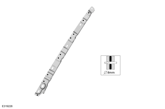
Ford Escape 2020-2026 Service Manual: Removal and Installation - Roof Rear Frame
Special Tool(s) / General Equipment 8 mm Drill Bit MIG/MAG Welding Equipment Spot Weld Drill Bit Locking Pliers Materials Name Specification Metal Bonding AdhesiveTA-1, TA-1-B, 3M™ 08115, LORD Fusor® 108B, Henkel Teroson EP 5055 - Removal WARNING: Electric vehicles damaged by a crash may have compromised high voltage safety systems an..
Categories
- Manuals Home
- 4th Generation Ford Escape Owners Manual
- 4th Generation Ford Escape Service Manual
- All-Wheel Drive
- Fuel Quality
- Accessing the Trip Computer. Resetting the Trip Computer
- New on site
- Most important about car
Under Hood Fuse Box
Locating the Under Hood Fuse Box

Accessing the Under Hood Fuse Box
