Ford Escape 2020-2026 Service Manual / Chassis / Steering System / Steering Wheel and Column Electrical Components / Removal and Installation - Steering Column Control Module (SCCM)
Ford Escape: Steering Wheel and Column Electrical Components / Removal and Installation - Steering Column Control Module (SCCM)
Removal
NOTE: Removal steps in this procedure may contain installation details.
-
NOTE: This step is only necessary when installing a new component.
NOTE: The PMI process must begin with the current SCCM installed. If the current SCCM does not respond to the diagnostic scan tool, the tool may prompt for As-Built Data as part of the repair.
Using a diagnostic scan tool, begin the PMI process for the SCCM following the on-screen instructions.
-
Remove the steering wheel.
Refer to: Steering Wheel (211-04 Steering Column, Removal and Installation).
-
Remove the steering column shrouds.
Refer to: Steering Column Shrouds (501-05 Interior Trim and Ornamentation, Removal and Installation).
-
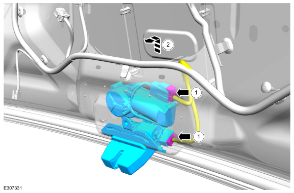
Disconnect the SCCM electrical connectors and position the wiring harness aside.
 |
-
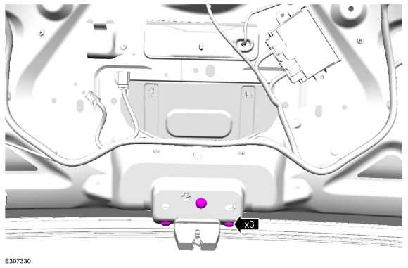
Remove the retainers and the SCCM .
Torque: 27 lb.in (3 Nm)
 |
Installation
-
To install, reverse the removal procedure.
-
NOTE: This step is only necessary when installing a new component.
Using a diagnostic scan tool, complete the PMI process for the SCCM following the on-screen instructions.
 Diagnosis and Testing - Steering Wheel and Column Electrical Components
Diagnostic Trouble Code (DTC) Chart
Diagnostics in this manual assume a certain skill level and knowledge of Ford-specific diagnostic practices. REFER to: Diagnostic Methods (100-00 General Information, Description and Operation)...
 Removal and Installation - Ignition Lock Cylinder Housing
Removal
Remove the SCCM .
Refer to: Steering Column Control Module (SCCM) (211-05 Steering Wheel
and Column Electrical Components, Removal and Installation)...
Other information:
Ford Escape 2020-2026 Service Manual: Description and Operation - Parking Aid - Overview
Overview - Active Park Assist The active park assist system is a full-assisted parking system. The system assists parking into and out (assist out of parking spots only available for parallel parking) of parking spaces. Sensors are used to detect parking spaces...
Ford Escape 2020-2026 Service Manual: General Procedures - Speaker Audio Test
Activation NOTE: The procedure used to download the audio files varies, depending on the web browser used. Using a suitable web browser, download all of the diagnostic sound tracks to a suitable USB drive. 125Hz Sample 100Hz Sample 80Hz Sample 63Hz Sample 50Hz Sample 40Hz Sample ..
Categories
- Manuals Home
- 4th Generation Ford Escape Owners Manual
- 4th Generation Ford Escape Service Manual
- Switching the Lane Keeping System On and Off. Switching the Lane Keeping System Mode. Alert Mode
- Child Safety Locks
- Fuel Quality
- New on site
- Most important about car
Under Hood Fuse Box
Locating the Under Hood Fuse Box

Accessing the Under Hood Fuse Box

Copyright © 2026 www.fordescape4.com