Ford Escape: Engine / Installation - Engine
Special Tool(s) / General Equipment
 |
303-476
(T94P-9472-A)
Socket, Exhaust Gas Oxygen Sensor TKIT-1994-LM/M TKIT-1994-F TKIT-1994-FLM/FM |
| Floor Crane | |
| Adjustable Mounting Arm | |
| Hose Clamp Remover/Installer | |
| Fluid Container | |
| Powertrain Jack | |
| Wooden Block | |
Materials
| Name | Specification |
|---|---|
| Motorcraft® High Temperature Nickel Anti-Seize Lubricant XL-2 |
- |
-
Inspect the engine block dowels. If the dowels are damaged or missing, install new engine block dowels.
 |
-
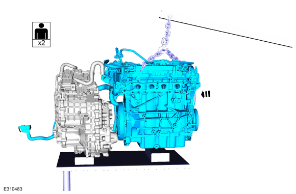
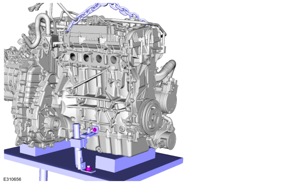
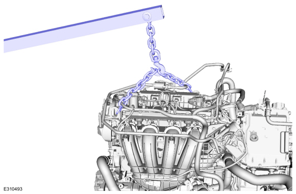
Install the engine to the transmission.
Use the General Equipment: Floor Crane
 |
-
NOTE: If the transmission is not positioned on the dowel pins, damage to the transmission may occur.
If the dowel pins were pulled out of the engine block during removal, install new dowel pins in the engine block.
-
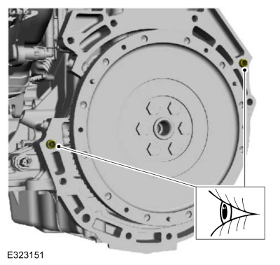
Install the RH engine to transmission bolts.
Torque: 35 lb.ft (48 Nm)
 |
-
Install theLH engine to transmission bolts.
Torque: 35 lb.ft (48 Nm)
 |
-
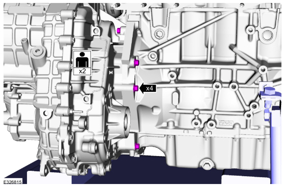
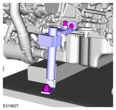
Install the RH adjustable mounting arm.
Use the General Equipment: Adjustable Mounting Arm
 |
-
Install the LH adjustable mounting arm.
Use the General Equipment: Adjustable Mounting Arm
 |
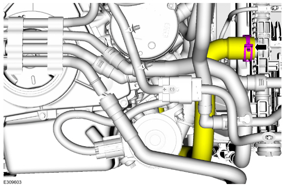
-
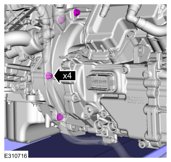
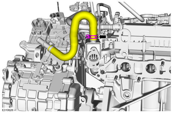
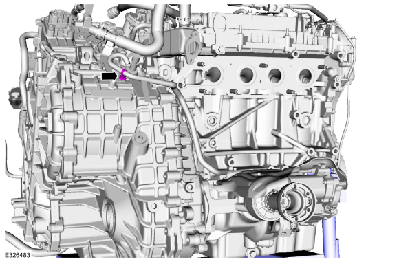
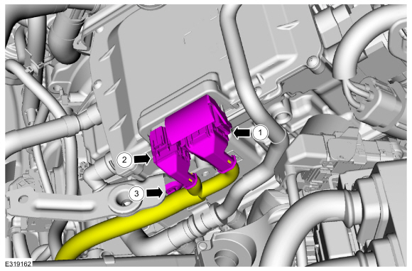
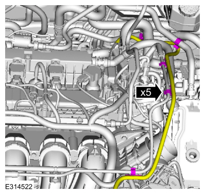
Install the EGR cooler hose.
 |
-
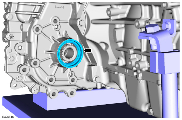
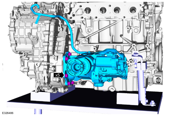
Install the new PTU to transmission compression seal.
 |
-
Install the PTU and bolts and hand tighten at this stage.
 |
-
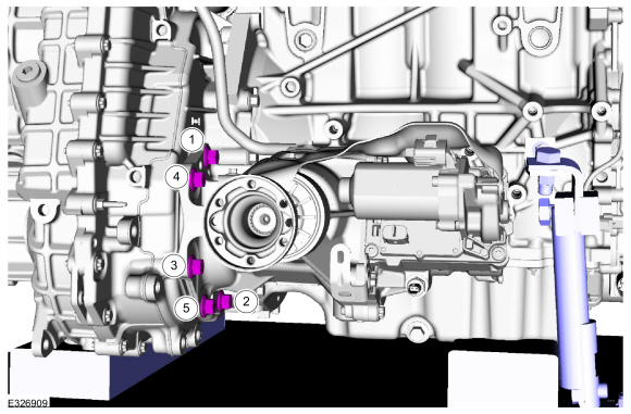
Tighten in the sequence shown.
Torque: 81 lb.ft (110 Nm)
 |
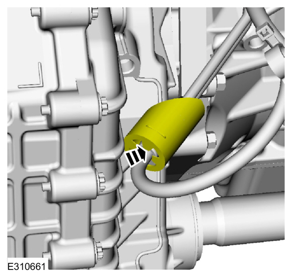
-
Install the vent hose retainer.
 |
-
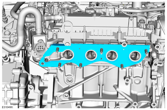
Install a new exhaust manifold gasket.
 |
-
Install new nuts and the exhaust manifold.
Torque: 41 lb.ft (55 Nm)
 |
-
Install the exhaust manifold heat shield and bolts.
Torque: 89 lb.in (10 Nm)
.jpg) |
-
Clean and inspect the gasket surface and the studs. Replace the studs if necessary.
Torque: 159 lb.in (18 Nm)
 |
-
Install the new EGR cooler inlet tube gaskets.
 |
-
Install the EGR cooler inlet tube and install the fasteners hand tight.
 |
-
Tighten in the sequence shown.
Torque:
1: 89 lb.in (10 Nm)
2: 18 lb.ft (24 Nm)
1: 18 lb.ft (24 Nm)
3: 89 lb.in (10 Nm)
4: 18 lb.ft (24 Nm)
3: 18 lb.ft (24 Nm)
.jpg) |
-
-
Calculate the correct torque wrench setting for the
following torque. Refer to Torque Wrench Adapter Formula in the Apex.
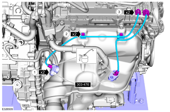
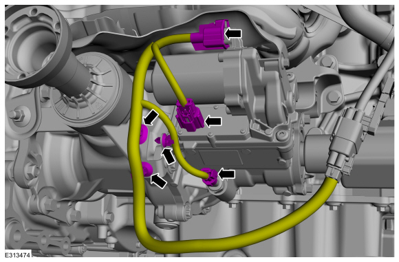
Install the HO2S .
Use Special Service Tool: 303-476 (T94P-9472-A) Socket, Exhaust Gas Oxygen Sensor.
Material: Motorcraft® High Temperature Nickel Anti-Seize Lubricant / XL-2
Torque: 35 lb.ft (48 Nm)
-
Install the bolts and wire connector brackets.
-
Connect the HO2S electrical connector.
-
Calculate the correct torque wrench setting for the
following torque. Refer to Torque Wrench Adapter Formula in the Apex.
Install the HO2S .
 |
-
Remove the Floor Crane and commercially available quick link and chain.
Use the General Equipment: Floor Crane
 |
-
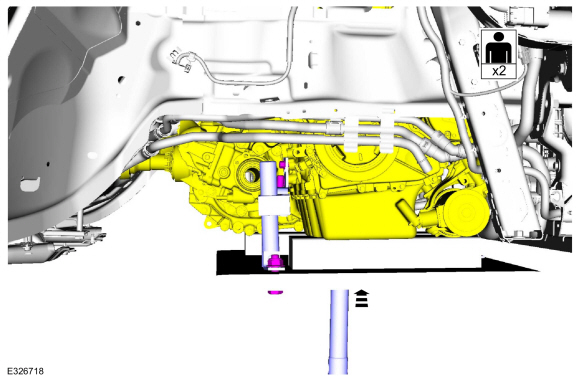
Install the engine and transmission into the vehicle.
Use the General Equipment: Powertrain Jack
Use the General Equipment: Adjustable Mounting Arm
Use the General Equipment: Wooden Block
 |
-
Install the transmission support insulator bolts finger tight.
.jpg) |
-
Hand start the engine mount fasteners.
-
Tighten the engine mount nuts.
Torque: 81 lb.ft (110 Nm)
-
Tighten the engine mount bolts.
Torque: 129 lb.ft (175 Nm)
-
Tighten the engine mount nuts.
 |
-
Tighten the transmission support insulator bolts.
Torque: 92 lb.ft (125 Nm)
|
-
Remove the adjustable mounting arm.
Use the General Equipment: Powertrain Jack
Use the General Equipment: Adjustable Mounting Arm
Use the General Equipment: Wooden Block
|
-
Remove the adjustable mounting arm and the powertrain jack.
Use the General Equipment: Powertrain Jack
Use the General Equipment: Adjustable Mounting Arm
Use the General Equipment: Wooden Block
 |
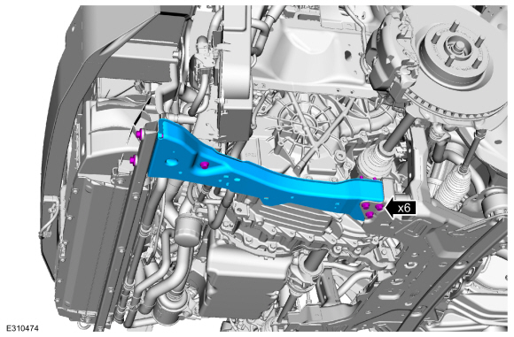
-
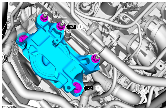
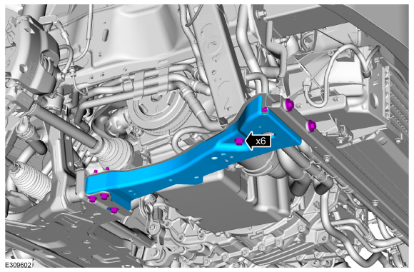
Install the front subframe.
Refer to: Front Subframe (502-00 Uni-Body, Subframe and Mounting System, Removal and Installation).
-
Install the roll restrictor bracket.
-
Install the stud and bolts.
Torque: 81 lb.ft (110 Nm)
-
Install the Clevis bolt.
Torque: 129 lb.ft (175 Nm)
-
Install the stud and bolts.
.jpg) |
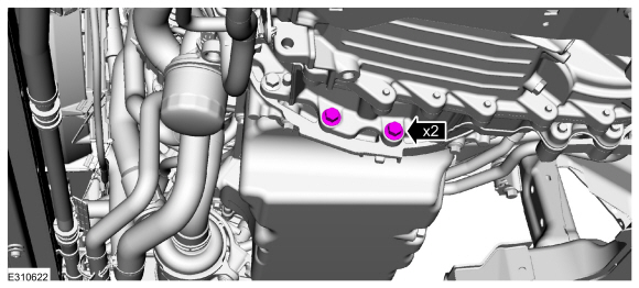
-
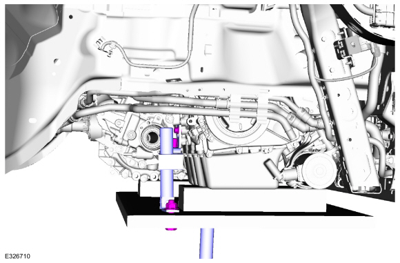
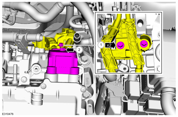
Install the PTU support bracket and bolts.
Torque: 35 lb.ft (48 Nm)
 |
-
Connect the PTU temperature sensor, motor connectors and retainers.
 |
-
Position back the driveshaft and make sure the installation marks are aligned.
 |
-
Install new PTU flange bolts.
Torque: 26 lb.ft (35 Nm)
.jpg) |
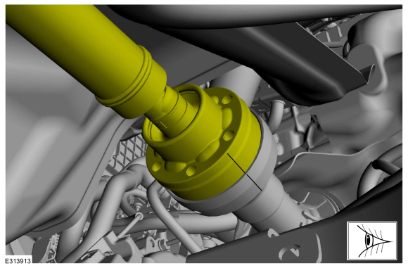
-
Install the intermediate shaft.
Refer to: Intermediate Shaft (205-04 Front Drive Halfshafts, Removal and Installation).
-
Install the LH front halfshaft.
Refer to: Front Halfshaft LH (205-04 Front Drive Halfshafts, Removal and Installation).
-
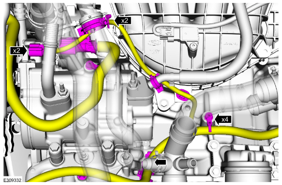
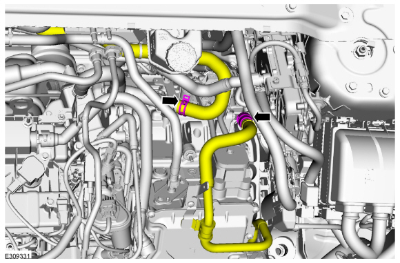
Install the coolant hoses.
Use the General Equipment: Hose Clamp Remover/Installer
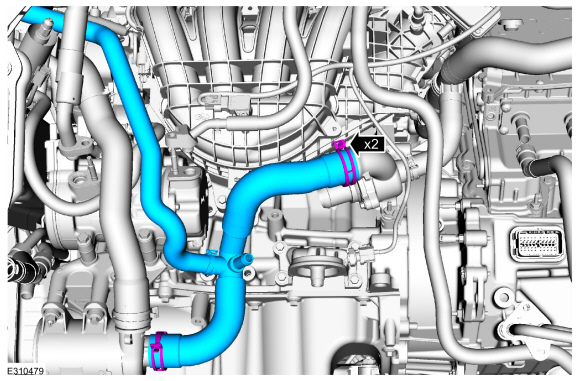 |
-
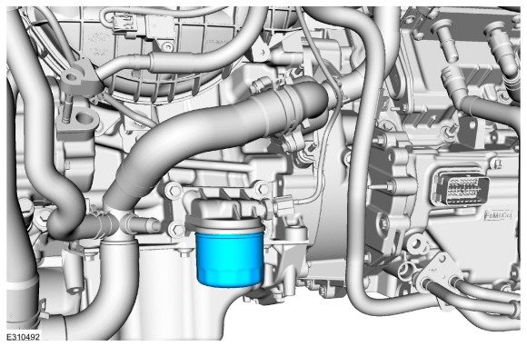
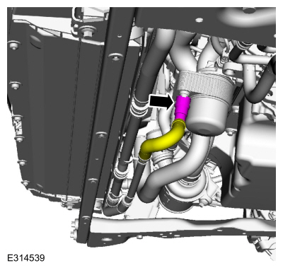
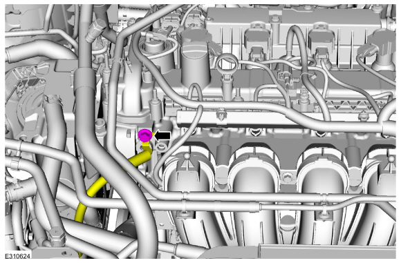
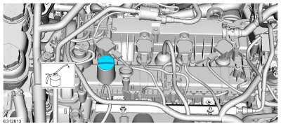
Install the engine oil filter.
Torque: 133 lb.in (15 Nm)
 |
-
Install new O-ring and gasket seals and the A/C line and nuts.
Torque: 159 lb.in (18 Nm)
.jpg) |
-
Install the transmission coolant line and bolt.
Use the General Equipment: Fluid Container
Torque: 18 lb.ft (25 Nm)
 |
-
Connect the upper radiator hose.
Use the General Equipment: Hose Clamp Remover/Installer
 |
-
NOTE: When connecting the coolant tube, push-click-pull on the coolant tubes to ensure proper connection.
Connect the coolant hose.
 |
-
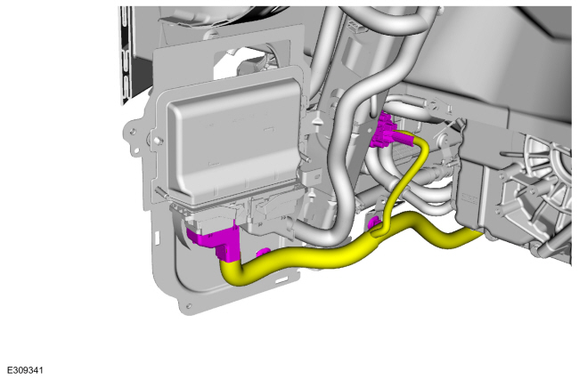
Connect the electrical connectors and install the wire harness retainers.
 |
-
Install the PCM cover and bolts.
.jpg) |
-
Connect the transmission electrical connector and install the wire harness retainers.
 |
-
-
Position back the wire harness bracket and install the bolts.
-
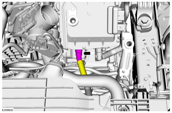
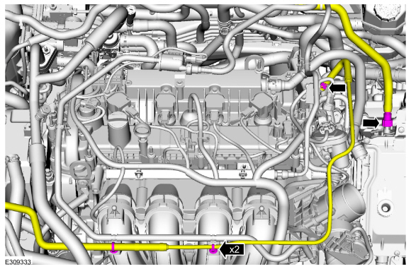
Connect the high voltage cable to the ISC and tighten the retainer.
Torque: 97 lb.in (11 Nm)
-
Position back the wire harness bracket and install the bolts.
 |
-
-
Connect C199A (40 pin connector) and engage the lever lock.
-
Connect C199B (22 pin connector).
-
Install the wire harness retainer.
-
Connect C199A (40 pin connector) and engage the lever lock.
 |
-
Connect the A/C electrical connectors and install the wire harness retainers.
 |
-
Connect the coolant pump electrical connector and install the wire harness retainers.
 |
-
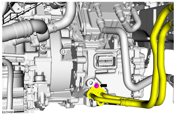
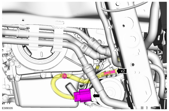
Install the coolant hoses and clips.
Use the General Equipment: Hose Clamp Remover/Installer
.jpg) |
-
If equipped.
Connect the oil cooler hose.
Use the General Equipment: Hose Clamp Remover/Installer
 |
-
Connect the coolant hose.
Use the General Equipment: Hose Clamp Remover/Installer
 |
-
Connect the coolant hose.
Use the General Equipment: Hose Clamp Remover/Installer
.jpg) |
-
If equipped with a block heater.
Connect the block heater electrical connector.
.jpg) |
-
If equipped with a block heater.
Position back the block heater electrical connector cover.
 |
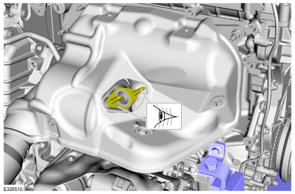
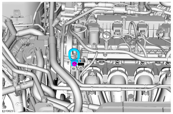
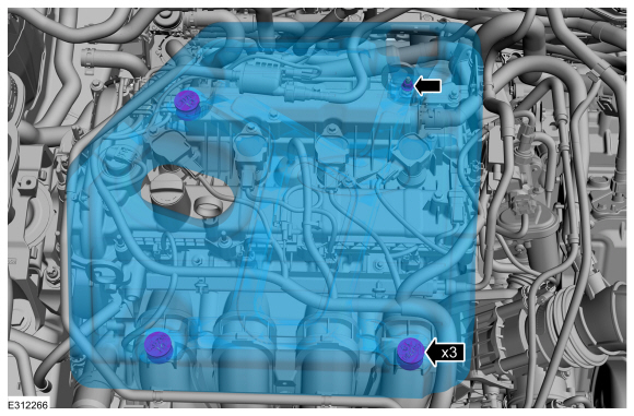
-
Install the oil pan bolts.
Torque: 35 lb.ft (48 Nm)
 |
-
Install the LH subframe support bracket and new bolts.
Torque: 22 lb.ft (30 Nm)
 |
-
Install the RH subframe support bracket and new bolts.
Torque: 22 lb.ft (30 Nm)
 |
-
Install the exhaust manifold bracket and bolts.
Torque: 18 lb.ft (25 Nm)
.jpg) |
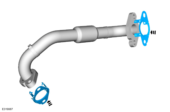
-
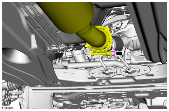
Install the new outlet clamp.
Torque: 17 lb.ft (23 Nm)
 |
-
Install the bracket and nuts.
Torque: 35 lb.ft (48 Nm)
.jpg) |
-
NOTICE: Do not excessively bend or twist the exhaust flexible pipe. Failure to follow these instructions may cause damage to the flexible pipe.
Remove the exhaust flexible pipe support.
 |
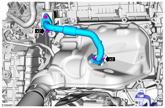
-
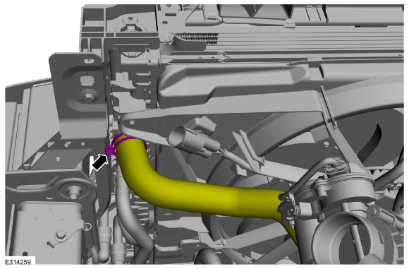
NOTE: When connecting the coolant tube, push-click-pull on the coolant tube to ensure proper connection.
Install the coolant hoses and the pin-type retainers.
Use the General Equipment: Hose Clamp Remover/Installer
 |
-
If equipped.
Position back the block heater wire harness and attach the clips.
 |
-
Remove the commercially available lift eye.
 |
-
Install the ground wire.
Torque: 133 lb.in (15 Nm)
 |
-
Connect the coolant hoses.
Use the General Equipment: Hose Clamp Remover/Installer
 |
-
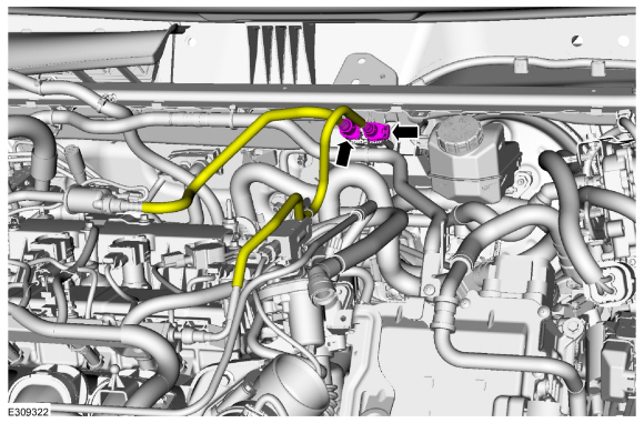
Connect the fuel vapor and fuel supply tubes.
Refer to: Quick Release Coupling (310-00C Fuel System - General Information, General Procedures).
Refer to: Spring Lock Couplings (310-00C Fuel System - General Information, General Procedures).
 |
-
-
Install the air cleaner.
-
Connect the air cleaner inlet tube.
-
Tighten the clamp.
-
Connect the vent tube.
-
Install the bolt.
-
Install the air cleaner.
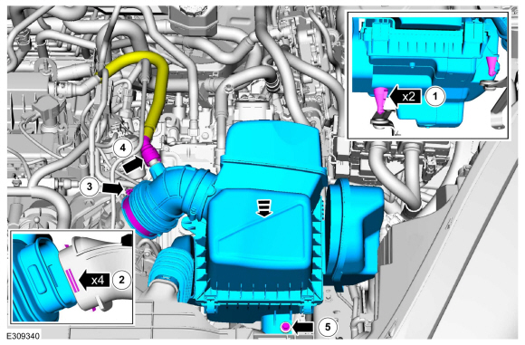 |
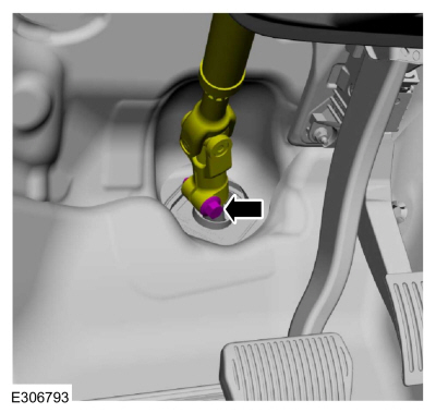
-
Position the steering column shaft and install a new bolt.
Torque: 46 lb.ft (63 Nm)
 |
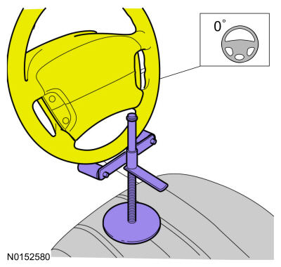
-
Using a holding device, hold the steering wheel in the straight-ahead position.
 |
-
Install the following items:
-
Install the degas bottle.
Refer to: Degas Bottle (303-03C Engine Cooling, Removal and Installation).
-
Install the front bumper cover.
Refer to: Front Bumper Cover (501-19 Bumpers, Removal and Installation).
-
Install the fender front fender splash shields.
Refer to: Fender Splash Shield (501-02 Front End Body Panels, Removal and Installation).
-
Install the degas bottle.
-
Fill the engine with clean engine oil.
Refer to: Specifications (303-03C Engine Cooling, Specifications).
 |
-
Connect the battery connectors.
Refer to: Battery Cables - 2.5L Duratec – Hybrid (121kW/164PS) (BG) (414-01 Battery, Mounting and Cables, Removal and Installation).
-
Repower the vehicle high-voltage system.
Refer to: High Voltage System De-energizing (414-03A High Voltage Battery, Mounting and Cables, General Procedures).
-
Pressurize the fuel system.
Refer to: Fuel System Pressure Release (310-00C Fuel System - General Information, General Procedures).
-
Fill and bleed the cooling system.
Refer to: Engine Cooling System Draining, Vacuum Filling and Bleeding (303-03C Engine Cooling, General Procedures).
-
Fill and bleed the Electric Powertrain Cooling System.
Refer to: Cooling System Filling and Bleeding (303-03D Electric Powertrain Cooling - Hybrid Electric Vehicle (HEV), General Procedures).
-
Charge the A/C system.
Refer to: Air Conditioning (A/C) System Recovery, Evacuation and Charging - 2.5L Duratec – Hybrid (121kW/164PS) (BG) (412-00 Climate Control System - General Information, General Procedures).
Refer to: Air Conditioning (A/C) System Recovery, Evacuation and Charging - Hybrid Electric Vehicle (HEV), Vehicles With: R134A Refrigerant (412-00 Climate Control System - General Information - 2.5L Duratec – Hybrid (121kW/164PS) (BG)) .
-
Check and fill the transmission fluid as necessary.
Refer to: Transmission Fluid Level Check (307-01B Automatic Transmission - Automatic Transmission – HF45, General Procedures).
-
Check the PTU (Power Transfer Case) fluid level.
Refer to: Front Halfshaft LH (205-04 Front Drive Halfshafts, Removal and Installation).
-
Install the undershield and fasteners.
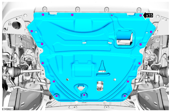 |
-
-
If the engine appearance cover stud bolt is loosened or
removed, it must be installed/tightened into the valve cover.
Torque: 62 lb.in (7 Nm)
-
Position the engine appearance cover onto the engine with the grommets aligned with the studs.
-
Press down on the engine appearance cover at each grommet location to attach the grommets onto the studs.
-
Install the engine appearance cover nut.
Torque: 44 lb.in (5 Nm)
-
If the engine appearance cover stud bolt is loosened or
removed, it must be installed/tightened into the valve cover.
 |
-
Start the vehicle and check the exhaust system for leaks.
-
If the engine was disassembled, perform the Misfire Monitor Neutral Profile Correction procedure.


Other information:
Ford Escape 2020-2026 Service Manual: Diagnosis and Testing - Collision Warning and Collision Avoidance System
Symptom Chart Symptom Chart: Forward Collision Warning Diagnostics in this manual assume a certain skill level and knowledge of Ford-specific diagnostic practices. REFER to: Diagnostic Methods (100-00 General Information, Description and Operation). Symptom Chart Condition Possible Sources Actions The forward collision warning syst..
Ford Escape 2020-2026 Service Manual: Removal and Installation - High Voltage Battery Cables - Plug-In Hybrid Electric Vehicle (PHEV)
Removal WARNING: To prevent the risk of high-voltage shock, always follow precisely all warnings and service instructions, including instructions to depower the system. The high-voltage system utilizes approximately 450 volts DC, provided through high-voltage cables to its components and modules. The high-voltage cables and wiring are identified by orange harness tape or orange wi..
Categories
- Manuals Home
- 4th Generation Ford Escape Owners Manual
- 4th Generation Ford Escape Service Manual
- Opening and Closing the Hood
- Accessing the Trip Computer. Resetting the Trip Computer
- Locating the Pre-Collision Assist Sensors
- New on site
- Most important about car
Fastening the Seatbelts

Copyright © 2026 www.fordescape4.com