Ford Escape: Front Disc Brake / Removal and Installation - Brake Caliper Anchor Plate
Removal
 WARNING:
Service actions on vehicles equipped with electronic brake
booster and electronic parking brakes may cause unexpected brake
application, which could result in injury to hands or fingers. Put the
brake system into service mode prior to servicing or removing any brake
components. Failure to follow this instruction may result in serious
personal injury.
WARNING:
Service actions on vehicles equipped with electronic brake
booster and electronic parking brakes may cause unexpected brake
application, which could result in injury to hands or fingers. Put the
brake system into service mode prior to servicing or removing any brake
components. Failure to follow this instruction may result in serious
personal injury.
NOTE: Removal steps in this procedure may contain installation details.
Vehicle with Electric Brake Booster
-
Activate the brake service mode.
Refer to: Brake Service Mode Activation and Deactivation (206-00 Brake System - General Information, General Procedures).
All vehicles
-
Remove the wheel and tires.
Refer to: Wheel and Tire (204-04A Wheels and Tires, Removal and Installation).
Vehicles without adhesive on brake pad insulator
-
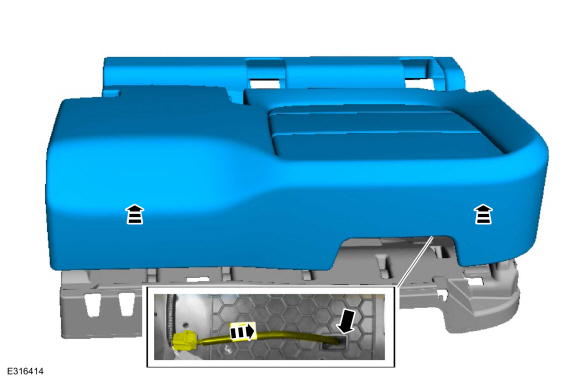
Remove the brake caliper spring.
 |
-
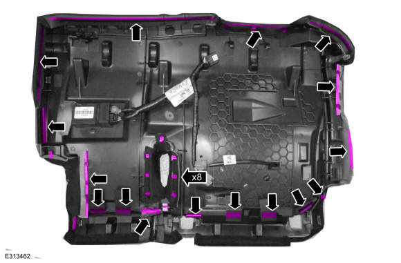
Remove the caps.
 |
-
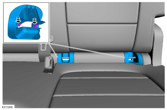
Remove the brake caliper guide pin bolts and the brake caliper.
Torque: 21 lb.ft (28 Nm)
 |
-
Remove the brake pads.
 |
Vehicles with adhesive on brake pad insulator
-
Remove the brake pads.
Refer to: Brake Pads (206-03 Front Disc Brake, Removal and Installation).
All vehicles
-
Remove the bolts and the brake caliper anchor plate.
Torque: 81 lb.ft (110 Nm)
 |
Installation
-
To install, reverse the removal procedure.
Vehicle with Electric Brake Booster
-
Deactivate the brake service mode.
Refer to: Brake Service Mode Activation and Deactivation (206-00 Brake System - General Information, General Procedures).

 Removal and Installation - Brake Disc
Materials
Name
Specification
Motorcraft® Metal Brake Parts CleanerPM-4-A, PM-4-B, APM-4-C
-
Removal
WARNING:
Service actions on vehicles equipped with electronic brake
booster and electronic parking brakes may cause unexpected brake
application, which could result in injury to hands or fingers...
Other information:
Ford Escape 2020-2026 Service Manual: Disassembly and Assembly - Front Bumper Cover
Special Tool(s) / General Equipment Hot Air Gun DISASSEMBLY Remove the front bumper cover. Refer to: Front Bumper Cover (501-19 Bumpers, Removal and Installation). On both sides. Remove the screws, release the tabs and remove the stone deflector...
Ford Escape 2020-2026 Service Manual: Diagnosis and Testing - Suspension System
Symptom Chart: Suspension System Diagnostics in this manual assume a certain skill level and knowledge of Ford-specific diagnostic practices.REFER to: Diagnostic Methods (100-00 General Information, Description and Operation). Condition Actions Wander GO to Pinpoint Test A Front bottoming or riding low GO to Pinpoint T..
Categories
- Manuals Home
- 4th Generation Ford Escape Owners Manual
- 4th Generation Ford Escape Service Manual
- All-Wheel Drive
- Plug-In Hybrid Electric Vehicle Drive Modes
- Child Safety Locks
- New on site
- Most important about car
Push Button Ignition Switch

Switching the Ignition Off
When the ignition is on or in accessory mode, press the push button ignition switch once without your foot on the brake pedal.