Ford Escape: Front Disc Brake / Removal and Installation - Brake Disc
Materials
| Name | Specification |
|---|---|
| Motorcraft® Metal Brake Parts Cleaner PM-4-A, PM-4-B, APM-4-C |
- |
Removal
 WARNING:
Service actions on vehicles equipped with electronic brake
booster and electronic parking brakes may cause unexpected brake
application, which could result in injury to hands or fingers. Put the
brake system into service mode prior to servicing or removing any brake
components. Failure to follow this instruction may result in serious
personal injury.
WARNING:
Service actions on vehicles equipped with electronic brake
booster and electronic parking brakes may cause unexpected brake
application, which could result in injury to hands or fingers. Put the
brake system into service mode prior to servicing or removing any brake
components. Failure to follow this instruction may result in serious
personal injury.
NOTE: Removal steps in this procedure may contain installation details.
Vehicle with Electric Brake Booster
-
Activate the brake service mode.
Refer to: Brake Service Mode Activation and Deactivation (206-00 Brake System - General Information, General Procedures).
All vehicles
-
Remove the wheel and tire.
Refer to: Wheel and Tire (204-04A Wheels and Tires, Removal and Installation).
-
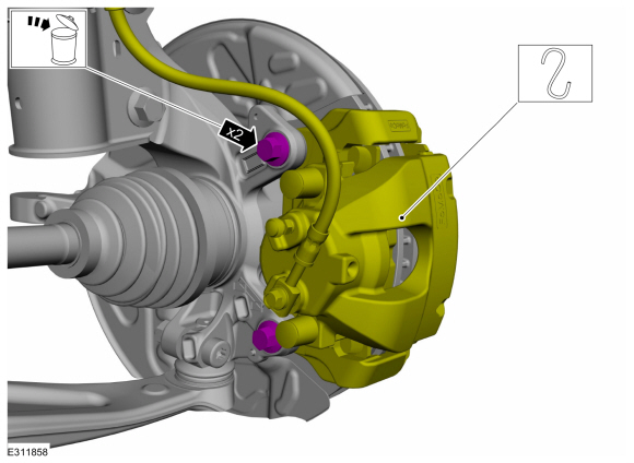
NOTICE: Make sure that no load is placed on the brake hose.
Remove the bolts and position the brake caliper and anchor plate aside.
Torque: 81 lb.ft (110 Nm)
 |
-
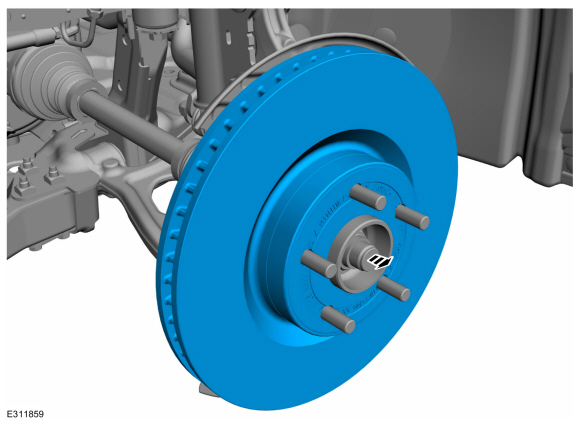
Remove the brake disc.
 |
Installation
-
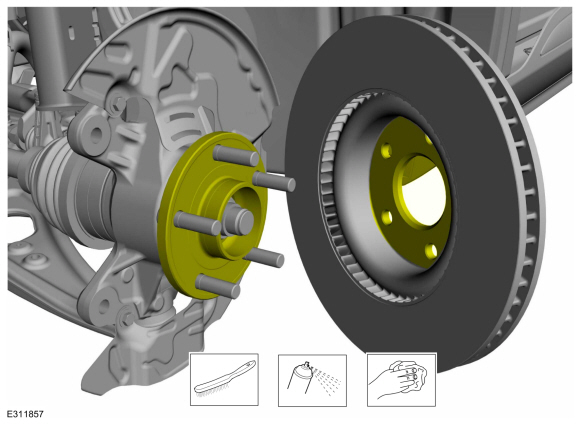
Clean the brake disc mating surfaces using a wire brush and the specified material.
Material: Motorcraft® Metal Brake Parts Cleaner / PM-4-A, PM-4-B, APM-4-C
 |
-
To install, reverse the removal procedure.
Vehicle with Electric Brake Booster
-
Deactivate the brake service mode.
Refer to: Brake Service Mode Activation and Deactivation (206-00 Brake System - General Information, General Procedures).
All vehicles
-
Apply the brake pedal several times to verify correct brake system operation.
 Removal and Installation - Brake Caliper Anchor Plate
Removal
WARNING:
Service actions on vehicles equipped with electronic brake
booster and electronic parking brakes may cause unexpected brake
application, which could result in injury to hands or fingers...
 Removal and Installation - Brake Disc Shield
Removal
NOTE:
Removal steps in this procedure may contain installation details.
Remove the brake disc.
Refer to: Brake Disc (206-03 Front Disc Brake, Removal and Installation)...
Other information:
Ford Escape 2020-2026 Service Manual: Removal and Installation - Drive Pinion Flange
Special Tool(s) / General Equipment 205-126 (T78P-4851-A) Holding Fixture, Drive Pinion Flange 205-233 (T85T-4851-AH) Installer, Drive Pinion FlangeTKIT-1985-FH-1 303-249Remover, Crankshaft Timing Pulley Transmission Jack Flat-Bladed Screwdriver Wooden Block Materials Name Specification Motorcraft® Premium Long-Life GreaseXG-1-E1 ESA-M1C..
Ford Escape 2020-2026 Owners Manual: Opening and Closing the Sun Shade
WARNING: Do not leave children unattended in your vehicle and do not let them play with the sun shades. Failure to follow this instruction could result in personal injury. The controls are on the overhead console. Opening the Sun Shade Press and release the switch to activate the one-touch open feature. To stop movement, press the switch a second time. The sun shade also opens when you op..
Categories
- Manuals Home
- 4th Generation Ford Escape Owners Manual
- 4th Generation Ford Escape Service Manual
- Opening and Closing the Hood
- Removal and Installation - All-Wheel Drive (AWD) Module - 1.5L EcoBoost (132kW/180PS) – I3 (Y1)/2.0L EcoBoost (177kW/240PS) – MI4
- Child Safety Locks
- New on site
- Most important about car
Vehicle Identification
Locating the Vehicle Identification Number
The vehicle identification number is on the left-hand side of the instrument panel.
