Ford Escape: Front End Sheet Metal Repairs / Removal and Installation - Fender Apron Panel Reinforcement
Special Tool(s) / General Equipment
| Resistance Spotwelding Equipment | |
| 8 mm Drill Bit | |
| MIG/MAG Welding Equipment | |
| Spot Weld Drill Bit | |
| Locking Pliers |
Materials
| Name | Specification |
|---|---|
| Metal Bonding Adhesive TA-1, TA-1-B, 3M™ 08115, LORD Fusor® 108B, Henkel Teroson EP 5055 |
- |
Removal
.jpg) WARNING:
Electric vehicles damaged by a crash may have compromised
high voltage safety systems and present a potential high voltage
electrical shock hazard. Exercise caution and wear appropriate Personal
Protective Equipment (PPE) safety gear, including high voltage safety
gloves and boots. Remove all metallic jewelry, including watches and
rings. Isolate the HV system as directed by the Ford Emergency Response
Guide for the vehicle. Failure to follow these instructions may result
in serious personal injury or death.
WARNING:
Electric vehicles damaged by a crash may have compromised
high voltage safety systems and present a potential high voltage
electrical shock hazard. Exercise caution and wear appropriate Personal
Protective Equipment (PPE) safety gear, including high voltage safety
gloves and boots. Remove all metallic jewelry, including watches and
rings. Isolate the HV system as directed by the Ford Emergency Response
Guide for the vehicle. Failure to follow these instructions may result
in serious personal injury or death.
NOTICE: Battery electric vehicle (BEV), hybrid electric vehicle (HEV) and plug-in hybrid electric vehicle (PHEV) contain a high-voltage battery. Before cutting or welding near the high-voltage battery it must be removed to avoid damage.
NOTE: Left hand (LH) side shown, right hand (RH) side similar.
NOTE: The fender apron panel is constructed of dual phase (DP) 600 steel and sectioning is possible. The following assumes full component replacement. Adjust to meet repair needs.
-
Refer to: Health and Safety Precautions (100-00 General Information, Description and Operation).
WARNING:
Before beginning any service procedure in this
manual, refer to health and safety warnings in section 100-00 General
Information. Failure to follow this instruction may result in serious
personal injury.
Refer to: High Voltage System Health and Safety Precautions - Overview (100-00 General Information, Description and Operation).
-
Depower the SRS .
Refer to: Supplemental Restraint System (SRS) Depowering (501-20B Supplemental Restraint System, General Procedures).
-
Remove the hood.
Refer to: Hood (501-02 Front End Body Panels, Removal and Installation).
-
Remove the front fender and splash shield.
Refer to: Fender (501-02 Front End Body Panels, Removal and Installation).
Refer to: Fender Splash Shield (501-02 Front End Body Panels, Removal and Installation).
-
Remove the cowl.
Refer to: Cowl Panel Grille (501-02 Front End Body Panels, Removal and Installation).
-
Remove the front bumper.
Refer to: Front Bumper (501-19 Bumpers, Removal and Installation).
-
Remove the cooling module.
Refer to: Cooling Module (303-03A Engine Cooling - 1.5L EcoBoost (132kW/180PS) – I3 (Y1), Removal and Installation).
Refer to: Cooling Module (303-03B Engine Cooling - 2.0L EcoBoost (177kW/240PS) – MI4, Removal and Installation).
Refer to: Cooling Module (303-03C Engine Cooling, Removal and Installation).
-
Remove the engine.
Refer to: Engine (303-01A Engine - 1.5L EcoBoost (132kW/180PS) – I3 (Y1), Removal).
Refer to: Engine (303-01B Engine - 2.0L EcoBoost (177kW/240PS) – MI4, Removal).
Refer to: Engine (303-01C Engine, Removal).
-
If Necessary:
Dimensionally restore the vehicle to pre-damage condition.
Refer to: Body and Frame (501-26 Body Repairs - Vehicle Specific Information and Tolerance Checks, Description and Operation).
-
Remove the fender apron panel.
Refer to: Fender Apron Panel (501-27 Front End Sheet Metal Repairs, Removal and Installation).
-
Remove the welds.
Use the General Equipment: Spot Weld Drill Bit
.jpg) |
-
Remove the welds.
Use the General Equipment: Spot Weld Drill Bit
.jpg) |
-
Remove the welds.
Use the General Equipment: Spot Weld Drill Bit
.jpg) |
-
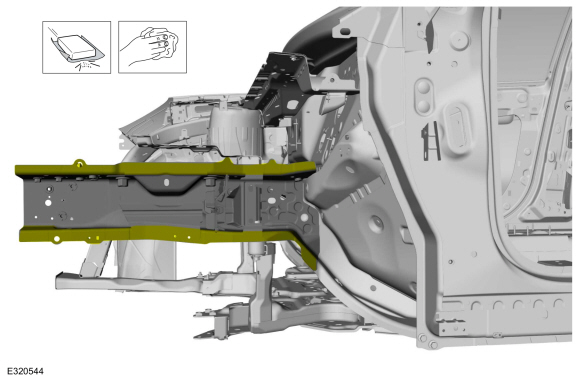
NOTE: Pay particular attention to the location of adhesives, sealers and noise, vibration and harness (NVH) materials to aid in installation.
Remove the fender apron panel reinforcement.
.jpg) |
Installation
WARNING:
Electric vehicles damaged by a crash may have compromised
high voltage safety systems and present a potential high voltage
electrical shock hazard. Exercise caution and wear appropriate Personal
Protective Equipment (PPE) safety gear, including high voltage safety
gloves and boots. Remove all metallic jewelry, including watches and
rings. Isolate the HV system as directed by the Ford Emergency Response
Guide for the vehicle. Failure to follow these instructions may result
in serious personal injury or death.
NOTICE: Battery electric vehicle (BEV), hybrid electric vehicle (HEV) and plug-in hybrid electric vehicle (PHEV) contain a high-voltage battery. Before cutting or welding near the high-voltage battery it must be removed to avoid damage.
NOTICE: The high-voltage battery in a battery electric vehicle (BEV), hybrid electric vehicle (HEV) or plug-in hybrid electric vehicle (PHEV) can be affected and damaged by excessively high temperatures. The temperature in some body shop paint booths can exceed 60° C (140° F). Therefore, during refinishing operations, the paint booth temperature must set at or below 60° C (140° F) with a bake time of 45 minutes or less. Temperatures in excess of 60° C (140° F) or bake durations longer than 45 minutes will require the high-voltage battery be removed from the vehicle prior to placing in the paint booth.
NOTICE: If refinishing cure temperatures exceed 60° C (140° F), the charge port light ring on plug-in vehicles must be removed.
NOTE: Factory welds may be substituted with resistance or metal inert gas (MIG) plug welds. Resistance welds may not be placed directly over original location. They must be placed adjacent to original location and match factory welds in quantity. Metal inert gas (MIG) plug welds must equal factory welds in both location and quantity.
NOTE: Left hand (LH) side shown, right hand (RH) side similar.
-
Refer to: Health and Safety Precautions (100-00 General Information, Description and Operation).
WARNING:
Before beginning any service procedure in this
manual, refer to health and safety warnings in section 100-00 General
Information. Failure to follow this instruction may result in serious
personal injury.
Refer to: High Voltage System Health and Safety Precautions - Overview (100-00 General Information, Description and Operation).
-
Sand to remove old adhesive, e-coat and clean.
 |
-
Drill plug weld holes.
Use the General Equipment: 8 mm Drill Bit
.jpg) |
-
Apply adhesive.
Material: Metal Bonding Adhesive / TA-1, TA-1-B, 3M™ 08115, LORD Fusor® 108B, Henkel Teroson EP 5055
.jpg) |
-
Install, properly position and clamp the service part.
Use the General Equipment: Locking Pliers
.jpg) |
-
Install the welds.
Use the General Equipment: Resistance Spotwelding Equipment
.jpg) |
-
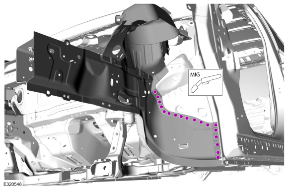
Install the welds.
Use the General Equipment: MIG/MAG Welding Equipment
.jpg) |
-
Install the welds.
Use the General Equipment: MIG/MAG Welding Equipment
 |
-
Install the fender apron panel.
Refer to: Fender Apron Panel (501-27 Front End Sheet Metal Repairs, Removal and Installation).
-
Dress all welds using typical metal finishing techniques.
-
Refinish the entire repair using a Ford approved paint system.
-
Restore corrosion protection.
Refer to: Corrosion Prevention (501-25 Body Repairs - General Information, General Procedures).
-
Install the engine.
Refer to: Engine (303-01A Engine - 1.5L EcoBoost (132kW/180PS) – I3 (Y1), Installation).
Refer to: Engine (303-01B Engine - 2.0L EcoBoost (177kW/240PS) – MI4, Installation).
Refer to: Engine (303-01 Engine) .
-
Install the cooling module.
Refer to: Cooling Module (303-03A Engine Cooling - 1.5L EcoBoost (132kW/180PS) – I3 (Y1), Removal and Installation).
Refer to: Cooling Module (303-03B Engine Cooling - 2.0L EcoBoost (177kW/240PS) – MI4, Removal and Installation).
Refer to: Cooling Module (303-03C Engine Cooling, Removal and Installation).
-
Install the front fender and splash shield.
Refer to: Fender (501-02 Front End Body Panels, Removal and Installation).
Refer to: Fender Splash Shield (501-02 Front End Body Panels, Removal and Installation).
-
Install the cowl panel.
Refer to: Cowl Panel Grille (501-02 Front End Body Panels, Removal and Installation).
-
Install the hood.
Refer to: Hood (501-02 Front End Body Panels, Removal and Installation).
-
Install the front bumper and bumper cover.
Refer to: Front Bumper (501-19 Bumpers, Removal and Installation).
Refer to: Front Bumper Cover (501-19 Bumpers, Removal and Installation).
-
Repower the SRS .
Refer to: Supplemental Restraint System (SRS) Repowering (501-20B Supplemental Restraint System, General Procedures).

 Removal and Installation - Front Side Member
Special Tool(s) /
General Equipment
Resistance Spotwelding Equipment
8 mm Drill Bit
MIG/MAG Welding Equipment
Spot Weld Drill Bit
Locking Pliers
Removal
WARNING:
Electric vehicles damaged by a crash may have compromised
high voltage safety systems and present a potential high voltage
electrical shock hazard...
Other information:
Ford Escape 2020-2026 Owners Manual: Steering
Electric Power Steering Electric Power Steering Precautions WARNING: The electric power steering system has diagnostic checks that continuously monitor the system. If a fault is detected, a message displays in the information display. Stop your vehicle as soon as it is safe to do so...
Ford Escape 2020-2026 Service Manual: Removal and Installation - Turbocharger Oil Supply Tube
Materials Name Specification Motorcraft® Metal Brake Parts CleanerPM-4-A, PM-4-B, APM-4-C - Removal NOTICE: The turbocharger compressor vanes can be damaged by even the smallest particles. When removing any turbocharger or engine air intake system component, ensure that no debris enters the system...
Categories
- Manuals Home
- 4th Generation Ford Escape Owners Manual
- 4th Generation Ford Escape Service Manual
- Power Outlet - Vehicles With: 12V Power Outlet
- Fuel Quality
- Description and Operation - Identification Codes
- New on site
- Most important about car
Vehicle Identification
Locating the Vehicle Identification Number
The vehicle identification number is on the left-hand side of the instrument panel.
