Ford Escape 2020-2026 Service Manual / Body and Paint / Body and Paint / Interior Trim and Ornamentation / Removal and Installation - Front Door Trim Panel
Ford Escape: Interior Trim and Ornamentation / Removal and Installation - Front Door Trim Panel
Special Tool(s) / General Equipment
| Pick Hook | |
| Interior Trim Remover |
Removal
NOTE: LH (left hand) shown, RH (right hand) similar.
NOTE: Removal steps in this procedure may contain installation details.
-
NOTICE: The door latch must be in the locked position prior to disassembly or the door lock feature may not function correctly after installation.
Lock the doors.
-
Release the clips and remove the interior front door handle bolt cover.
Use the General Equipment: Pick Hook
 |
-
Remove the interior front door handle bolt.
Torque: 40 lb.in (4.5 Nm)
.jpg) |
-
Remove the window control switch.
Refer to: Driver Door Window Control Switch (501-11 Glass, Frames and Mechanisms, Removal and Installation).
Refer to: Passenger Door Window Control Switch (501-11 Glass, Frames and Mechanisms, Removal and Installation).
-
Remove the front door trim panel bolts.
Torque: 48 lb.in (5.4 Nm)
.jpg) |
-
Release the tab and remove the front door trim panel bolt cover.
Use the General Equipment: Pick Hook
.jpg) |
-
Remove the front door trim panel bolt.
Torque: 8 lb.in (0.9 Nm)
.jpg) |
-
Remove the front door trim panel lower bolts.
Torque: 13 lb.in (1.5 Nm)
.jpg) |
-
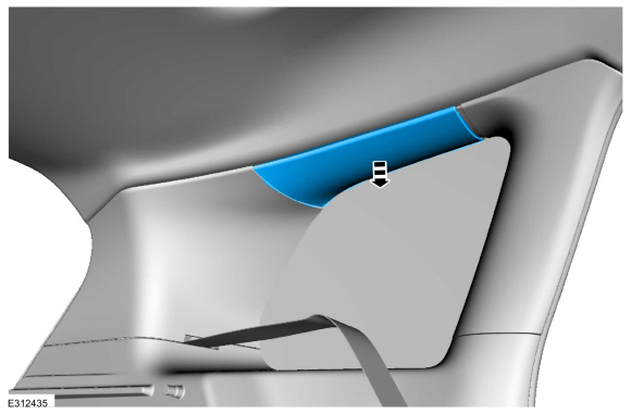
Release front door trim panel clips.
Use the General Equipment: Interior Trim Remover
.jpg) |
-
NOTICE: For re-installation, the retention tab must be re-engaged to prevent the interior front door handle from becoming non-functional.
Remove the front door trim panel.
-
Disengage the retention tab.
-
Position the interior front door cable aside.
-
Disconnect the front door lock control switch electrical connector.
-
If equipped.
Disconnect the front door ambient light electrical connector.
-
Disengage the retention tab.
.jpg) |
Installation
-
NOTE: Transfer parts as necessary.
To install, reverse the removal procedure.
 Removal and Installation - C-Pillar Trim Panel
Special Tool(s) /
General Equipment
Interior Trim Remover
Removal
NOTE:
LH (left hand) shown, RH (right hand) similar.
NOTE:
Removal steps in this procedure may contain installation details...
 Removal and Installation - Front Scuff Plate Trim Panel
Special Tool(s) /
General Equipment
Interior Trim Remover
Removal
NOTE:
LH (left hand) shown, RH (right hand) similar.
LH (left hand) Side
Remove the hood latch release handle...
Other information:
Ford Escape 2020-2026 Owners Manual: Federal Highway Administration Regulation
Regulations such as those issued by the Federal Highway Administration or issued pursuant to the Occupational Safety and Health Act (OSHA), and state and local laws and regulations may require additional equipment for the way you intend to use your vehicle...
Ford Escape 2020-2026 Service Manual: Removal and Installation - Cruise Control Module (CCM)
Removal NOTE: Removal steps in this procedure may contain installation details. Remove the front bumper cover. Refer to: Front Bumper Cover (501-19 Bumpers, Removal and Installation). Remove the air deflector. Remove the pushpins...
Categories
- Manuals Home
- 4th Generation Ford Escape Owners Manual
- 4th Generation Ford Escape Service Manual
- Power Outlet - Vehicles With: 12V Power Outlet
- All-Wheel Drive
- General Procedures - Transmission Fluid Level Check
- New on site
- Most important about car
Push Button Ignition Switch

Switching the Ignition Off
When the ignition is on or in accessory mode, press the push button ignition switch once without your foot on the brake pedal.
Copyright © 2026 www.fordescape4.com