Ford Escape: Front Seats / Removal and Installation - Front Seat Backrest Cover
Special Tool(s) / General Equipment
| Hog Ring Plier |
Removal
 WARNING:
Front seat backrest trim covers installed on seats equipped
with seat side airbags cannot be repaired. A new trim cover must be
installed. Cleaning is permissible. Failure to follow these instructions
may result in the seat side airbag deploying incorrectly and increase
the risk of serious personal injury or death in a crash.
WARNING:
Front seat backrest trim covers installed on seats equipped
with seat side airbags cannot be repaired. A new trim cover must be
installed. Cleaning is permissible. Failure to follow these instructions
may result in the seat side airbag deploying incorrectly and increase
the risk of serious personal injury or death in a crash.
NOTE: Driver seat shown, passenger seat similar.
-
Remove the side airbag.
Refer to: Side Airbag (501-20B Supplemental Restraint System, Removal and Installation).
-
Remove the front head restraint guide sleeves.
Refer to: Front Head Restraint Guide Sleeve (501-10A Front Seats, Removal and Installation).
Vehicles with heated seats
-
-
Disconnect the front seat backrest heater mat electrical connector.
-
Detach the front seat backrest heater mat wiring harness retainer and position aside.
-
Disconnect the front seat backrest heater mat electrical connector.
.jpg) |
All seats
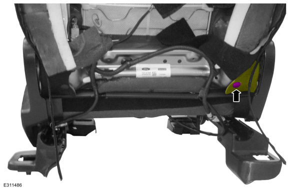
-
Remove the pin-type retainer and position the backrest cover aside.
 |
-
Detach the front seat backrest cover upper J-clip.
.jpg) |
-
Remove the front seat backrest cover and foam as an assembly.
.jpg) |
-
NOTE: This step is only necessary when installing a new component.
Remove the front seat backrest cover.
-
Invert the backrest cover.
-
Remove the hog rings.
-
NOTICE: Use care when separating the seat backrest trim cover from the hook-and-loop strips or the hook-and-loop strips may be torn from the seat backrest foam.
Release the hook-and-loop strips.
-
Invert the backrest cover.
.jpg) |
Installation
-
To install, reverse the removal procedure.
- Use the General Equipment: Hog Ring Plier
.jpg) |
 Removal and Installation - Front Seat Backrest
Removal
WARNING:
The following procedure describes critical repair steps
required for correct seat component installation. Follow all notes and
steps carefully...
 Removal and Installation - Front Seat Control Switch
Removal
NOTE:
Driver seat shown, passenger seat similar.
Remove the front seat.
Refer to: Front Seat (501-10A Front Seats, Removal and Installation)...
Other information:
Ford Escape 2020-2026 Service Manual: Diagnosis and Testing - Wipers and Washers
Diagnostic Trouble Code (DTC) Chart Diagnostics in this manual assume a certain skill level and knowledge of Ford-specific diagnostic practices. Module DTC Description Action BCM B130F:12 Run Accessory Control: Circuit Short To Battery GO to Pinpoint Test A BCM B130F:14 Run Accessory Control: Circuit Short To Ground Or Open GO to Pinpoint Test A BCM B13A4:11 Front ..
Ford Escape 2020-2026 Owners Manual: Using Your Cell Phone
Recent Call List Display and select an entry from a list of previous calls. Contacts Display a smart search form to look up your contacts. Use the List button to alphabetically sort your contacts. Favorites Display and select an entry from the list of favorite contacts that are set up on your phone. Messaging Displays the list of text messages to read, listen to, or respond to. Email Display..
Categories
- Manuals Home
- 4th Generation Ford Escape Owners Manual
- 4th Generation Ford Escape Service Manual
- Drive Modes
- Adjusting the Headlamps
- Plug-In Hybrid Electric Vehicle Drive Modes
- New on site
- Most important about car
Under Hood Fuse Box
Locating the Under Hood Fuse Box

Accessing the Under Hood Fuse Box
