Ford Escape: Front End Sheet Metal Repairs / Removal and Installation - Front Side Member Section
Special Tool(s) /
General Equipment
| Resistance Spotwelding Equipment |
| Spherical Cutter |
| Air Body Saw |
| MIG/MAG Welding Equipment |
| Spot Weld Drill Bit |
| Locking Pliers |
Removal
.jpg) WARNING:
Electric vehicles damaged by a crash may have compromised
high voltage safety systems and present a potential high voltage
electrical shock hazard. Exercise caution and wear appropriate Personal
Protective Equipment (PPE) safety gear, including high voltage safety
gloves and boots. Remove all metallic jewelry, including watches and
rings. Isolate the HV system as directed by the Ford Emergency Response
Guide for the vehicle. Failure to follow these instructions may result
in serious personal injury or death.
WARNING:
Electric vehicles damaged by a crash may have compromised
high voltage safety systems and present a potential high voltage
electrical shock hazard. Exercise caution and wear appropriate Personal
Protective Equipment (PPE) safety gear, including high voltage safety
gloves and boots. Remove all metallic jewelry, including watches and
rings. Isolate the HV system as directed by the Ford Emergency Response
Guide for the vehicle. Failure to follow these instructions may result
in serious personal injury or death.
NOTICE:
Battery electric vehicle (BEV), hybrid electric vehicle
(HEV) and plug-in hybrid electric vehicle (PHEV) contain a high-voltage
battery. Before cutting or welding near the high-voltage battery it must
be removed to avoid damage.
NOTE:
Left hand (LH) side shown, right hand (RH) side similar.
NOTE:
The front side member is constructed from a Taylor welded
blank. No sectioning may occur at the laser weld line. If damage extends
rearward of the laser line, the entire frame member must be replaced at
factory seams.
-
WARNING:
Before beginning any service procedure in this
manual, refer to health and safety warnings in section 100-00 General
Information. Failure to follow this instruction may result in serious
personal injury.
Refer to: Health and Safety Precautions (100-00 General Information, Description and Operation).
Refer to: High Voltage System Health and Safety Precautions - Overview (100-00 General Information, Description and Operation).
-
Depower the SRS .
Refer to: Supplemental Restraint System (SRS) Depowering (501-20B Supplemental Restraint System, General Procedures).
-
Remove the front bumper.
Refer to: Front Bumper (501-19 Bumpers, Removal and Installation).
-
Remove the hood, fender and fender splash shield.
Refer to: Hood (501-02 Front End Body Panels, Removal and Installation).
Refer to: Fender (501-02 Front End Body Panels, Removal and Installation).
Refer to: Fender Splash Shield (501-02 Front End Body Panels, Removal and Installation).
-
Remove the engine cooling module.
Refer to: Cooling Module (303-03A Engine Cooling - 1.5L EcoBoost (132kW/180PS) – I3 (Y1), Removal and Installation).
Refer to: Cooling Module (303-03B Engine Cooling - 2.0L EcoBoost (177kW/240PS) – MI4, Removal and Installation).
Refer to: Cooling Module (303-03C Engine Cooling, Removal and Installation).
-
If Necessary:
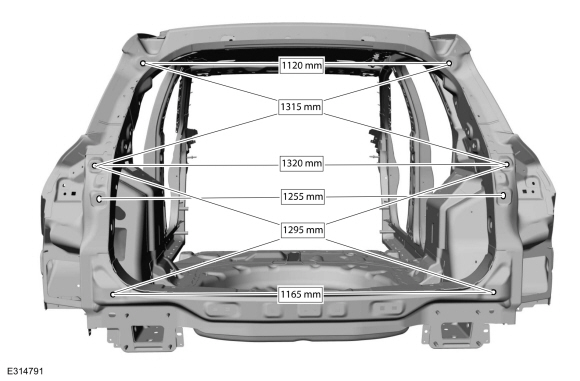
Dimensionally restore the vehicle to pre-damage condition.
Refer to: Body and Frame (501-26 Body Repairs - Vehicle Specific Information and Tolerance Checks, Description and Operation).
-
Remove the welds.
Use the General Equipment: Spot Weld Drill Bit
-
Remove the welds.
Use the General Equipment: Spot Weld Drill Bit
-
Remove the bumper bracket.
-
Remove the welds.
Use the General Equipment: Spot Weld Drill Bit
-
Remove the bolts.
-
Remove the bolts.
-
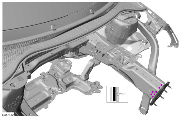
Carefully measure 50 mm forward from the laser weld line and cut the inner frame member.
Use the General Equipment: Air Body Saw
Use the General Equipment: Spherical Cutter
-
Remove the welds.
Use the General Equipment: Spot Weld Drill Bit
-
Remove the inner side member section.
-
Carefully measure as indicated and cut the outer side member.
Use the General Equipment: Air Body Saw
Use the General Equipment: Spherical Cutter
-
Remove the welds.
Use the General Equipment: Spot Weld Drill Bit
-
Remove the outer side member section.
Installation
WARNING:
Electric vehicles damaged by a crash may have compromised
high voltage safety systems and present a potential high voltage
electrical shock hazard. Exercise caution and wear appropriate Personal
Protective Equipment (PPE) safety gear, including high voltage safety
gloves and boots. Remove all metallic jewelry, including watches and
rings. Isolate the HV system as directed by the Ford Emergency Response
Guide for the vehicle. Failure to follow these instructions may result
in serious personal injury or death.
NOTICE:
Battery electric vehicle (BEV), hybrid electric vehicle
(HEV) and plug-in hybrid electric vehicle (PHEV) contain a high-voltage
battery. Before cutting or welding near the high-voltage battery it must
be removed to avoid damage.
NOTICE:
The high-voltage battery in a battery electric vehicle
(BEV), hybrid electric vehicle (HEV) or plug-in hybrid electric vehicle
(PHEV) can be affected and damaged by excessively high temperatures. The
temperature in some body shop paint booths can exceed 60° C (140° F).
Therefore, during refinishing operations, the paint booth temperature
must set at or below 60° C (140° F) with a bake time of 45 minutes or
less. Temperatures in excess of 60° C (140° F) or bake durations longer
than 45 minutes will require the high-voltage battery be removed from
the vehicle prior to placing in the paint booth.
NOTICE:
If refinishing cure temperatures exceed 60° C (140° F), the
charge port light ring on plug-in vehicles must be removed.
NOTE:
Factory welds may be substituted with resistance or metal
inert gas (MIG) plug welds. Resistance welds may not be placed directly
over original location. They must be placed adjacent to original
location and match factory welds in quantity. Metal inert gas (MIG) plug
welds must equal factory welds in both location and quantity.
NOTE:
Left hand (LH) side shown, right hand (RH) side similar.
-
WARNING:
Before beginning any service procedure in this
manual, refer to health and safety warnings in section 100-00 General
Information. Failure to follow this instruction may result in serious
personal injury.
Refer to: Health and Safety Precautions (100-00 General Information, Description and Operation).
Refer to: High Voltage System Health and Safety Precautions - Overview (100-00 General Information, Description and Operation).
-
Cut the service part to fit the repair area.
Use the General Equipment: Air Body Saw
Use the General Equipment: Spherical Cutter
-
Install, properly position and clamp the inner side member section.
Use the General Equipment: Locking Pliers
-
NOTE:
The use of a backer plate in welding is recommended.
Completely seam weld the sectioning joint.
Use the General Equipment: MIG/MAG Welding Equipment
-
Cut the service part to fit the repair area.
Use the General Equipment: Air Body Saw
Use the General Equipment: Spherical Cutter
-
Install, properly position and clamp the outer side member section.
Use the General Equipment: Locking Pliers
-
NOTE:
The use of a backer plate in welding is recommended.
Completely seam weld the sectioning joint.
Use the General Equipment: MIG/MAG Welding Equipment
-
Dress all welds using typical metal finishing techniques and materials.
-
Install the welds.
Use the General Equipment: Resistance Spotwelding Equipment
-
Install, properly position and clamp the bumper bracket.
Use the General Equipment: Locking Pliers
-
Install the welds.
Use the General Equipment: Resistance Spotwelding Equipment
-
Install the welds.
Use the General Equipment: Resistance Spotwelding Equipment
-
Install the welds.
Use the General Equipment: Resistance Spotwelding Equipment
-
Install the bolts.
Torque:
18 lb.ft (25 Nm)
-
Install the bolts.
Torque:
18 lb.ft (25 Nm)
-
Refinish the entire repair using a Ford approved paint system.
-
Restore corrosion protection.
Refer to: Corrosion Prevention (501-25 Body Repairs - General Information, General Procedures).
-
Install the engine cooling module.
Refer to: Cooling Module (303-03A Engine Cooling - 1.5L EcoBoost (132kW/180PS) – I3 (Y1), Removal and Installation).
Refer to: Cooling Module (303-03B Engine Cooling - 2.0L EcoBoost (177kW/240PS) – MI4, Removal and Installation).
Refer to: Cooling Module (303-03C Engine Cooling, Removal and Installation).
-
Install the hood, fender and fender splash shield.
Refer to: Fender (501-02 Front End Body Panels, Removal and Installation).
Refer to: Fender Splash Shield (501-02 Front End Body Panels, Removal and Installation).
Refer to: Hood (501-02 Front End Body Panels, Removal and Installation).
-
Install the front bumper and bumper cover.
Refer to: Front Bumper (501-19 Bumpers, Removal and Installation).
Refer to: Front Bumper Cover (501-19 Bumpers, Removal and Installation).
-
Repower the SRS .
Refer to: Supplemental Restraint System (SRS) Repowering (501-20B Supplemental Restraint System, General Procedures).
Special Tool(s) /
General Equipment
Resistance Spotwelding Equipment
8 mm Drill Bit
MIG/MAG Welding Equipment
Spot Weld Drill Bit
Locking Pliers
Removal
WARNING:
Electric vehicles damaged by a crash may have compromised
high voltage safety systems and present a potential high voltage
electrical shock hazard...
Other information:
Diagnostic Trouble Code (DTC) Chart
Diagnostics in this manual assume a certain skill level and knowledge of Ford-specific diagnostic practices. REFER to: Diagnostic Methods (100-00 General Information, Description and Operation).
Diagnostic Trouble Code Chart
Module
DTC
Description
Action
PAM
B129E..
Special Tool(s) /
General Equipment
Locking Pliers
Removal
WARNING:
To prevent the risk of high-voltage shock, always follow
precisely all warnings and service instructions, including instructions
to depower the system. The high-voltage system utilizes approximately
450 volts DC, provided through high-voltage cables to its components and
modules. The high-voltage cables ..
.jpg)
.jpg)
.jpg)
.jpg)
.jpg)
.jpg)
.jpg)
.jpg)
.jpg)
.jpg)
.jpg)
.jpg)
.jpg)
.jpg)
.jpg)
.jpg)
.jpg)
.jpg)
.jpg)
.jpg)
.jpg)
 Removal and Installation - Front Side Member
 Air conditioning system