Ford Escape: Fuel Tank and Lines / Removal and Installation - Fuel Pump and Sender Unit
Special Tool(s) / General Equipment
 |
310-123 Locking Ring, Fuel Tank TKIT-2004J-F TKIT-2005U-LM |
Removal
.jpg)


.jpg) WARNING:
Do not smoke, carry lighted tobacco or have an open flame of
any type when working on or near any fuel-related component. Highly
flammable mixtures may be present and may be ignited. Failure to follow
these instructions may result in serious personal injury.
WARNING:
Do not smoke, carry lighted tobacco or have an open flame of
any type when working on or near any fuel-related component. Highly
flammable mixtures may be present and may be ignited. Failure to follow
these instructions may result in serious personal injury.
NOTE: Removal steps in this procedure may contain installation details.
-
Refer to: Gasoline and Gasoline-Ethanol Fuel Systems Health and Safety
Precautions (100-00 General Information, Description and Operation).
-
With the vehicle in NEUTRAL, position it on a hoist.
Refer to: Jacking and Lifting - Overview (100-02 Jacking and Lifting, Description and Operation).
-
Remove the Fuel Tank.
-
-
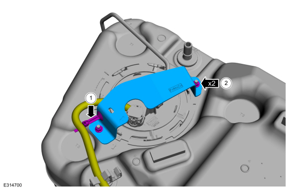
Detach the clip and postion the wiring harness aside.
-
Remove the nuts.
Torque: 80 lb.in (9 Nm)
-
Detach the clip and postion the wiring harness aside.
 |
-
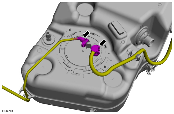
Disconnect the electrical connector and quick release coupling.
Refer to: Quick Release Coupling (310-00B Fuel System - General Information - 2.0L EcoBoost (177kW/240PS) – MI4, General Procedures).
 |
-
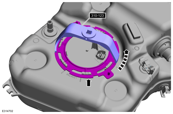
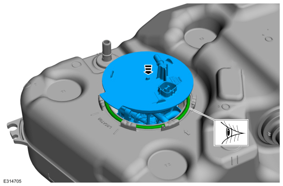
NOTE: Note the position of the component before removal.
Using the special tool remove the lock ring and the fuel pump and sender unit.
Use Special Service Tool: 310-123 Locking Ring, Fuel Tank.
 |
-
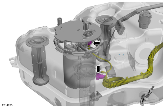
Lift the Fuel Pump and Sender unit slightly and disconnect the quick connector and the electrical connector.
Refer to: Quick Release Coupling (310-00B Fuel System - General Information - 2.0L EcoBoost (177kW/240PS) – MI4, General Procedures).
 |
-
NOTICE: Take extra care not to damage the fuel tank level sensor float and arm.
Remove and discard the O-ring.
.jpg) |
Installation
-
Reconnect the electrical connector and quick connector.
Refer to: Quick Release Coupling (310-00B Fuel System - General Information - 2.0L EcoBoost (177kW/240PS) – MI4, General Procedures).
|
-
NOTE: Use a new seal.
NOTE: Make sure that the seal is correctly located.
 |
-
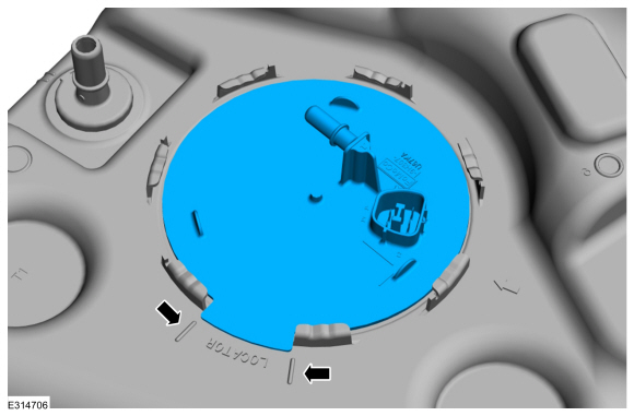
NOTE: Make sure that the installation marks are aligned.
 |
-
To install, reverse the removal procedure.
 Removal and Installation - Fuel Lines
Removal
WARNING:
Do not smoke, carry lighted tobacco or have an open flame of
any type when working on or near any fuel-related component...
 Removal and Installation - Fuel Tank
Special Tool(s) /
General Equipment
Powertrain Jack
Removal
WARNING:
Do not smoke, carry lighted tobacco or have an open flame of
any type when working on or near any fuel-related component...
Other information:
Ford Escape 2020-2026 Service Manual: Description and Operation - Supplemental Climate Control - System Operation and Component Description
System Operation Cabin Coolant Heater System SVG Information not available at this time. Item Description 1 Cabin Heater Coolant Temperature Sensor 2 PCM 3 BCMC 4 SOBDMC 5 Cabin Coolant Heater 6 Cabin Heater Coolant Diverter Valve 7 Cabin Heater Coolant Pump 8 Ambient Air Temperature (AAT) Sensor 9 Engine Coolan..
Ford Escape 2020-2026 Service Manual: Removal and Installation - Front Side Member Section
Special Tool(s) / General Equipment Resistance Spotwelding Equipment Spherical Cutter Air Body Saw MIG/MAG Welding Equipment Spot Weld Drill Bit Locking Pliers Removal WARNING: Electric vehicles damaged by a crash may have compromised high voltage safety systems and present a potential high voltage electrical shock hazard. Exercise caution and wear..
Categories
- Manuals Home
- 4th Generation Ford Escape Owners Manual
- 4th Generation Ford Escape Service Manual
- Switching the Rear Window Wiper On and Off. Reverse Wipe
- Opening and Closing the Hood
- Removal and Installation - All-Wheel Drive (AWD) Module - 1.5L EcoBoost (132kW/180PS) – I3 (Y1)/2.0L EcoBoost (177kW/240PS) – MI4
- New on site
- Most important about car
Push Button Ignition Switch

Switching the Ignition Off
When the ignition is on or in accessory mode, press the push button ignition switch once without your foot on the brake pedal.