Ford Escape: Front Suspension / Removal and Installation - Lower Arm
Special Tool(s) / General Equipment
| Vehicle/Axle Stands |
Removal
NOTICE: Suspension fasteners are critical parts that affect the performance of vital components and systems. Failure of these fasteners may result in major service expense. Use the same or equivalent parts if replacement is necessary. Do not use a replacement part of lesser quality or substitute design. Tighten fasteners as specified.
NOTE: Removal steps in this procedure may contain installation details.
-
Remove the wheel and tire.
Refer to: Wheel and Tire (204-04A Wheels and Tires, Removal and Installation).
-
If equipped.
Remove the bolts and the engine front undershield.
 |
-
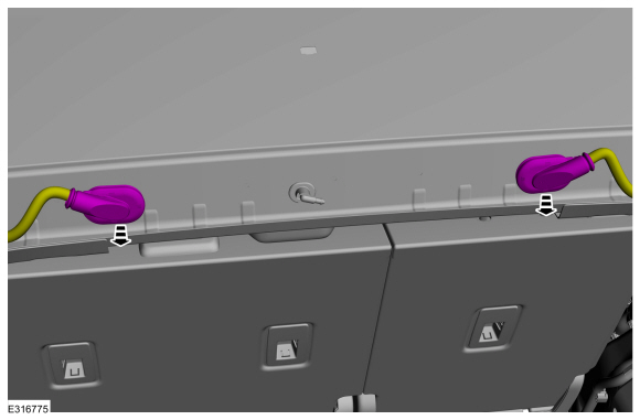
If equipped, On both sides.
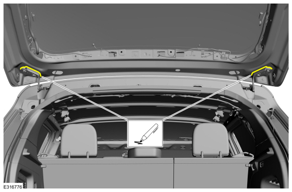
Remove the bolt and disconnect the ride height sensor from the front lower arm.
 |
-
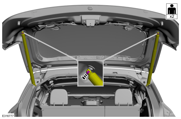
NOTICE: Do not use a prying device to open the slot in the knuckle to separate the lower ball joint from the knuckle assembly. Damage to the knuckle assembly may occur.
NOTICE: Do not use a prying device or separator fork between the ball joint and the wheel knuckle. Damage to the ball joint or ball joint seal may result. Only use the pry bar by inserting it into the lower arm body opening.
NOTICE: Use care when releasing the lower arm and wheel knuckle into the resting position or damage to the ball joint seal may occur.
NOTICE: Do not use power tools to remove or install the lower arm outboard nut. Damage to the ball joint or ball joint seal may occur.
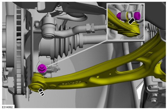
NOTE: Use the TORX PLUS® holding feature to prevent the ball stud from turning while removing or installing the lower arm outboard nut. Torx® and TORX PLUS® is a reg. tm of Acument Intellectual Properties, LLC.
Remove and discard the ball joint pinch bolt and nut and separate the lower arm from the wheel knuckle.
 |
-
Remove the front bumper cover.
Refer to: Front Bumper Cover (501-19 Bumpers, Removal and Installation).
-
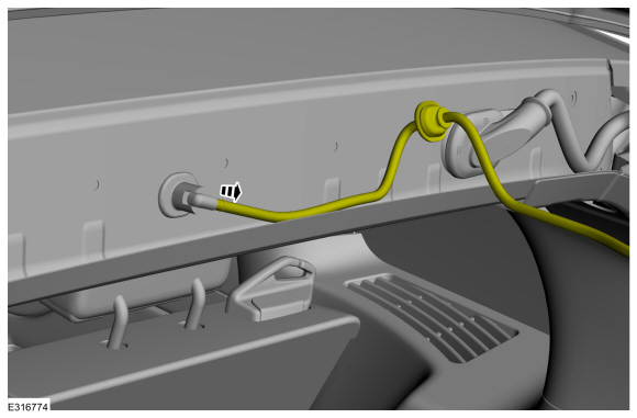
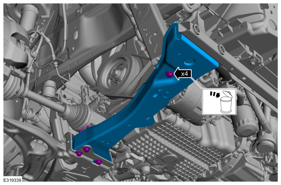
Remove the subframe support bracket bolts.
 |
-
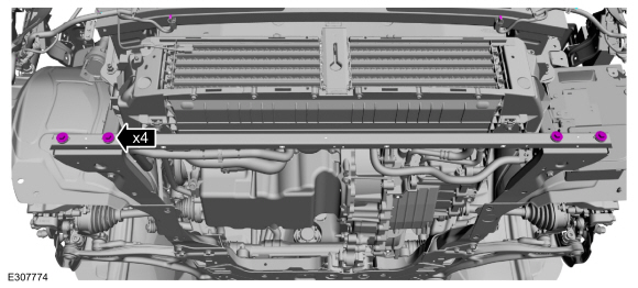
Remove and discard the bolts and remove the front outer side member.
 |
-
Remove the lower arm.
-
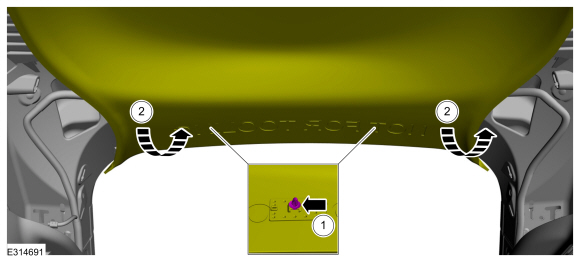
Remove and discard the lower arm forward bolt.
-
Remove and discard the lower arm rearward bolt and nut.
-
Remove and discard the lower arm forward bolt.
 |
Installation
NOTICE: Tighten the suspension fasteners with the weight of the vehicle on the wheels and tires or use a suitable jack to raise the suspension to curb height or damage to the bushings may occur.
-
NOTE: Only tighten the nuts and bolts finger tight at this stage.
Install the lower arm.
-
Install the new lower arm forward bolt.
-
Install the new lower arm rearward bolt and nut.
-
Install the new lower arm forward bolt.
 |
-
NOTICE: Do not use power tools to remove or install the lower arm outboard nut. Damage to the ball joint or ball joint seal may occur.
NOTE: Use the TORX PLUS® holding feature to prevent the ball stud from turning while removing or installing the lower arm outboard nut. Torx® and TORX PLUS® is a reg. tm of Acument Intellectual Properties, LLC.
NOTE: Make sure that the mating wheel knuckle face is clean and free of foreign material.
Attach the lower arm to the wheel knuckle and install the new ball joint pinch bolt and nut.
Torque: 66 lb.ft (90 Nm)
 |
-
Install the vehicle/axle stands to support the suspension at curb height.
Use the General Equipment: Vehicle/Axle Stands
 |
-
NOTICE: Tighten the suspension fasteners with the weight of the vehicle on the wheels and tires or use a suitable jack to raise the suspension to curb height or damage to the bushings may occur.
Tighten the lower arm bolts and nut.
-
Tighten the new lower arm forward bolt.
Torque:
Stage 1: 103 lb.ft (140 Nm)
Stage 2: 120°
-
Tighten the new rearward lower arm bolt and nut.
Torque:
Stage 1: 98 lb.ft (133 Nm)
Stage 2: 120°
-
Tighten the new lower arm forward bolt.
 |
-
Install the front outer side member with new bolts.
Torque: 22 lb.ft (30 Nm)
 |
-
Install the subframe support bracket bolts.
Torque: 22 lb.ft (30 Nm)
|
-
Install the front bumper cover.
Refer to: Front Bumper Cover (501-19 Bumpers, Removal and Installation).
-
If equipped, On both sides.
Install the bolt and the ride height sensor.
Torque: 97 lb.in (11 Nm)
|
-
If equipped.
Position the underbody shields and install the retainers.
Torque: 13 lb.in (1.5 Nm)
|
-
Install the wheel and tire.
Refer to: Wheel and Tire (204-04A Wheels and Tires, Removal and Installation).
-
Check and if necessary adjust front toe.
Refer to: Front Toe Adjustment (204-00 Suspension System - General Information, General Procedures).

 Removal and Installation - Lower Arm Bushing
Special Tool(s) /
General Equipment
204-830Remover/Installer, Bushing Lower Arm
204-833Remover/Installer, Bushing Lower Arm
204-834Remover/Installer, Front Lower Arm Bushing
Hydraulic Press
Wooden Block
Removal
NOTE:
Removal steps in this procedure may contain installation details...
Other information:
Ford Escape 2020-2026 Service Manual: Removal and Installation - Exhaust Gas Recirculation (EGR) Temperature Sensor
Removal NOTE: Removal steps in this procedure may contain installation details. Remove the air cleaner outlet pipe. Refer to: Air Cleaner Outlet Pipe (303-12C Intake Air Distribution and Filtering, Removal and Installation). Disconnect the electrical connector...
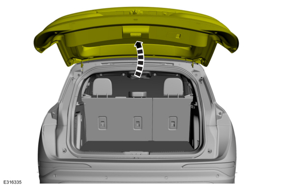
Ford Escape 2020-2026 Service Manual: Removal and Installation - Rear Gate Trunk Module (RGTM)
Removal NOTE: Removal steps in this procedure may contain installation details. NOTE: This step is only necessary when installing a new component. The PMI process must begin with the current RGTM installed. If the current RGTM does not respond to the diagnostic scan tool, the tool may prompt for As-Built Data as part of the repair...
Categories
- Manuals Home
- 4th Generation Ford Escape Owners Manual
- 4th Generation Ford Escape Service Manual
- Power Outlet - Vehicles With: 12V Power Outlet
- Child Safety Locks
- Plug-In Hybrid Electric Vehicle Drive Modes
- New on site
- Most important about car
Master Access Code
What Is the Master Access Code
The master access code is a factory-set five-digit entry code. You can operate the keypad with the master access code at any time. The master access code is on the owner’s wallet card in the glove box and is available from an authorized dealer.
Displaying the Master Access Code
To display the factory-set code in the information display:
