Ford Escape: Engine / Removal and Installation - Oil Pump
Special Tool(s) /
General Equipment
.jpg) |
303-290B-20
Adapter, Car-Bar
TKIT-2014D-ROW3
TKIT-2014D-FL_ROW |
 |
303-F070
Support Bar, Engine
TKIT-1999A-F/LT
TKIT-1999A-FM/FLM |
 |
303-F072
Support Bar, Engine |
| Oil Drain Equipment |
| Trolley Jack |
| Round-Ended Steel Rule |
| Wooden Block |
Materials
| Name |
Specification |
Motorcraft® High Performance Engine RTV Silicone
TA-357 |
WSE-M4G323-A6
|
Motorcraft® Metal Surface Prep Wipes
ZC-31-B |
-
|
Removal
-
With the vehicle in NEUTRAL, position it on a hoist.
Refer to: Jacking and Lifting - Overview (100-02 Jacking and Lifting, Description and Operation).
-
Remove the cowl panel grille.
Refer to: Cowl Panel Grille (501-02 Front End Body Panels, Removal and Installation).
-
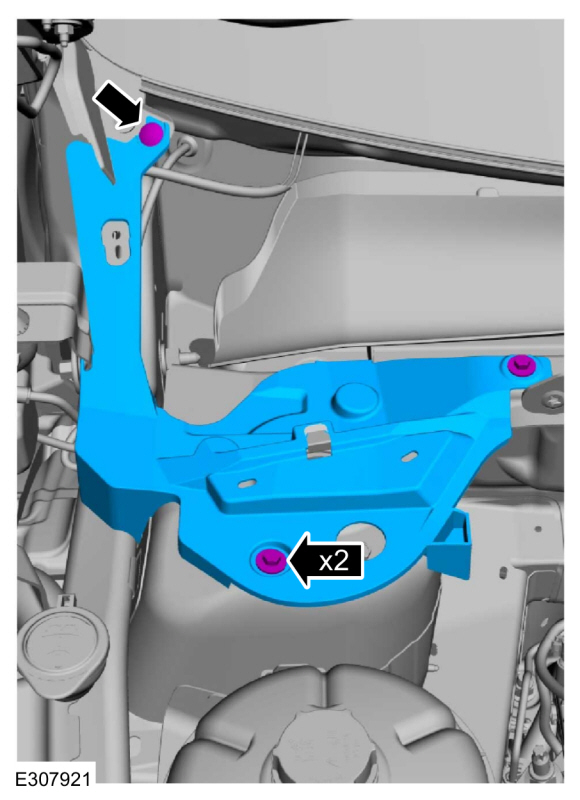
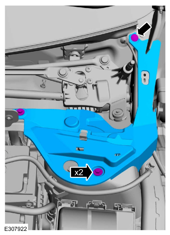
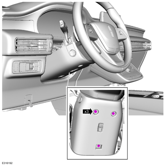
Remove the bolts, pin-type retainer and the RH cowl cover.
-
Remove the bolts, pin-type retainer and the LH cowl cover.
-
Remove the coolant pump.
Refer to: Coolant Pump (303-03C Engine Cooling, Removal and Installation).
-
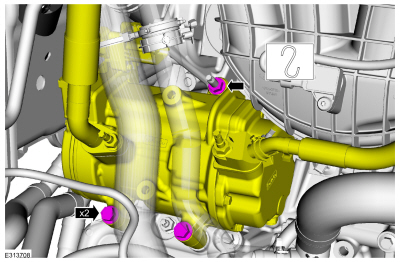
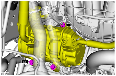
Disconnect the A/C compressor electrical connectors and pin-type retainers.
-
Remove the A/C compressor nut, bolts and position aside.
-
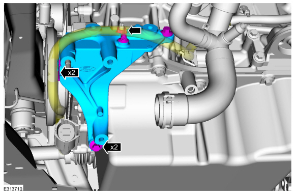
Disconnect the wire harness pin-type retainers, remove the fasteners and bracket.
-
Remove the engine front cover.
Refer to: Engine Front Cover (303-01C Engine, Removal and Installation).
-
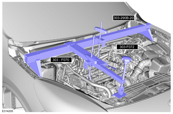
Using the feet from 303-F070 and the car bar adapters
303-290B-20 assemble them on the 303-F072 engine support bar and support
the engine.
Install Special Service Tool: 303-F072
Support Bar, Engine.
Install Suggested Tool: 303-290B-20
Adapter, Car-Bar. Tool shown or a commercially available equivalent can be used.
, 303-F070
Support Bar, Engine. Tool shown or a commercially available equivalent can be used.
-
Remove the General Equipment: Trolley Jack
Remove the General Equipment: Wooden Block
-
-
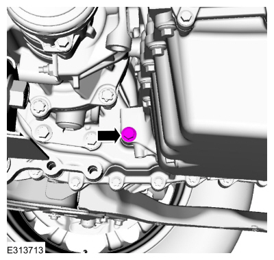
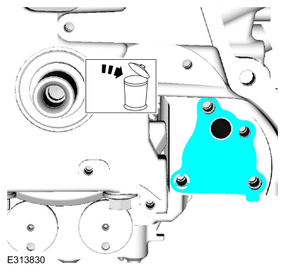
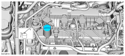
Remove the bolt and drain the engine oil.
Use the General Equipment: Oil Drain Equipment
-
Install the oil drain bolt.
Torque:
21 lb.ft (28 Nm)
-
Remove and discard the oil filter.
-
Remove the bolt.
-
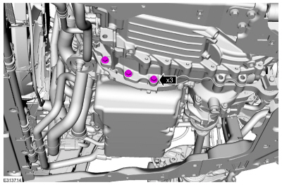
Remove the bolts.
-
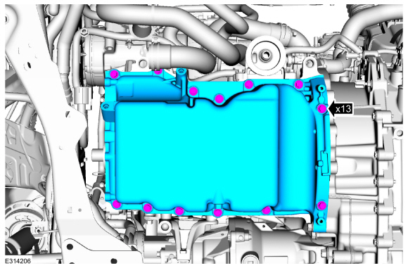
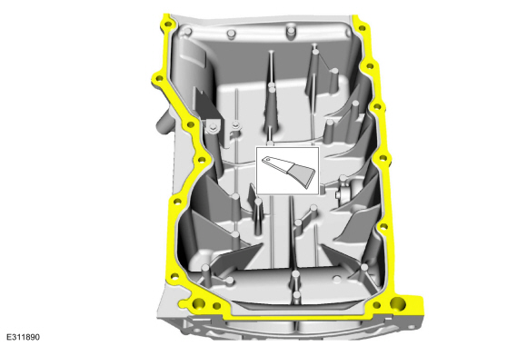
Remove the bolts and the oil pan.
-
Make sure that the mating surface is clean and free of foreign material.
Refer to: RTV Sealing Surface Cleaning and Preparation (303-00 Engine System - General Information, General Procedures).
-
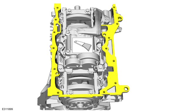
Make sure that the mating surface is clean and free of foreign material.
Refer to: RTV Sealing Surface Cleaning and Preparation (303-00 Engine System - General Information, General Procedures).
-
-
Remove the bolts and the oil pickup tube.
-
Remove and discard the oil pickup tube gasket.
-
-
Position out the spring.
-
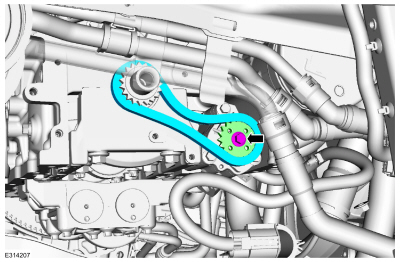
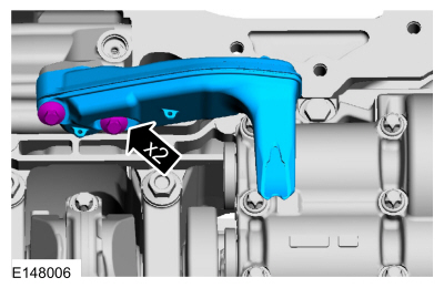
Remove the bolts and the oil pump chain tensioner.
-
-
Remove the chain from the oil pump drive gear.
-
Remove the bolt and the oil pump drive gear.
-
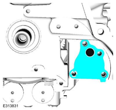
Remove the bolts and the oil pump.
-
Remove and discard the oil pump gasket.
Installation
-
Prime the oil pump. Add 2 tablespoons of clean engine oil to the oil pump and rotate the oil pump by hand.
-
Install the new oil pump gasket.
-
NOTE:
Clean the oil pump and cylinder block mating surfaces with Motorcraft® Metal Surface Prep.
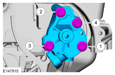
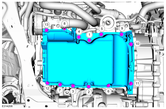
Install the oil pump and the bolts. Tighten in sequence shown in 2 stages.
Material: Motorcraft® Metal Surface Prep Wipes
/ ZC-31-B
Torque:
Stage 1:
89 lb.in (10 Nm)
Stage 2:
177 lb.in (20 Nm)
-
-
Install the oil pump drive gear and the bolt.
Torque:
18 lb.ft (25 Nm)
-
Install the chain onto the oil pump drive gear.
-
-
Install the oil pump chain tensioner and the bolts.
Torque:
89 lb.in (10 Nm)
-
Push the tensioner spring down and position the spring under the shoulder bolt.
-
Lubricate new gasket with clean engine oil and install.
-
Install the oil pickup tube and the bolts.
Torque:
89 lb.in (10 Nm)
-
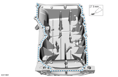
NOTE:
If the oil pan is not secured within 10 minutes of
sealant application, the sealant must be removed and the sealing area
cleaned with metal surface prep. Allow to dry until there is no sign of
wetness, or 10 minutes, whichever is longer. Failure to follow this
procedure can cause future oil leakage.
Apply a 3 mm (0.19 in) bead of silicone sealant.
Material: Motorcraft® High Performance Engine RTV Silicone
/ TA-357
(WSE-M4G323-A6)
-
NOTE:
Only tighten the bolts finger tight at this stage.
Install the oil pan and the bolts.
-
Using a straight edge, align the front surface of the oil pan flush with the front surface of the engine block.
Use the General Equipment: Round-Ended Steel Rule
-
Tighten the oil pan bolts in sequence shown.
Torque:
177 lb.in (20 Nm)
-
Install the bolts.
Torque:
35 lb.ft (48 Nm)
-
Install the bolt.
Torque:
35 lb.ft (48 Nm)
-
Install a new oil filter.
Torque:
133 lb.in (15 Nm)
-
NOTE:
Failure to position the wood block and floor jack as illustrated can result in damage to the oil pan.
Using a trolley jack and wooden block, support the engine.
Install the General Equipment: Trolley Jack
Install the General Equipment: Wooden Block
-
Remove the engine support bar.
Remove Special Service Tool: 303-F072
Support Bar, Engine.
, 303-290B-20
Adapter, Car-Bar.
Remove Suggested Tool: 303-F070
Support Bar, Engine.
-
Install the engine front cover.
Refer to: Engine Front Cover (303-01C Engine, Removal and Installation).
-
Install the bracket and fasteners and connect the electrical harness pin-type retainers.
Torque:
18 lb.ft (25 Nm)
-
Position the A/C compressor, install the nut and bolts.
Torque:
18 lb.ft (25 Nm)
-
Connect the A/C compressor electrical connectors and pin-type retainers.
-
Install the coolant pump.
Refer to: Coolant Pump (303-03C Engine Cooling, Removal and Installation).
-
Install the LH cowl cover, bolts and the pin-type retainer.
-
Install the RH cowl cover, bolts and the pin-type retainer.
-
Install the cowl panel grille.
Refer to: Cowl Panel Grille (501-02 Front End Body Panels, Removal and Installation).
-
Fill the engine with clean engine oil.
Refer to: Specifications (303-03C Engine Cooling, Specifications).
Materials
Name
Specification
Motorcraft® Thread Sealant with PTFETA-24-B
WSK-M2G350-A2
Removal
NOTE:
Removal steps in this procedure may contain installation details...
Removal
NOTE:
During engine repair procedures, cleanliness is extremely
important. Any foreign material, including any material created while
cleaning gasket surfaces, that enters the oil passages, coolant passages
or the oil pan can cause engine failure...
Other information:
Panoramic Roof Opening Panel
The roof opening panel consists of the following:
Air deflector
Front sliding glass panel (sunroof)
Front sliding glass panel motor (sunroof motor)
Shield (sunshade) assembly
Shield (sunshade) motor
Blinds (concertina blinds)
Roof panel fixed glass (panoramic)
Roof opening panel frame assembly
Roof opening panel control ..
WARNING: Depending on where
you secure a child restraint, and
depending on the child restraint design,
you may block access to certain seatbelt
buckle assemblies and LATCH lower
anchors, rendering those features
potentially unusable. To avoid risk of
injury, make sure occupants only use
seating positions where they are able to
be properly restrained.
Note: Although the child restraint
il..
Categories
What Is the Master Access Code
The master access code is a factory-set
five-digit entry code. You can operate the
keypad with the master access code at
any time. The master access code is on the
owner’s wallet card in the glove box and
is available from an authorized dealer.
Displaying the Master Access Code
To display the factory-set code in the
information display:

Remove the rubber mat.
Insert the first programmed key in the
backup slot.
Press the push button ignition switch
once and wait a few seconds.
Press the push button ignition switch
again and remove the key.
Within 10 seconds, place a second
programmed intelligent access key in
the backup slot and press the push
button ignition switch.
read more
.jpg)
.jpg)
.jpg)
.jpg)
.jpg)
.jpg)
.jpg)
.jpg)
 Removal and Installation - Oil Pressure Switch
 Removal and Installation - Timing Chain