Ford Escape: Front Drive Halfshafts / Removal and Installation - Front Halfshaft RH
Special Tool(s) / General Equipment
 |
204-161
(T97P-1175-A)
Installer, Halfshaft TKIT-1997-LM2 TKIT-1997-F/FM2 TKIT-1997-FLM2 |
 |
205-D070
(D93P-1175-B)
Remover, Front Wheel Hub |
| Tie Rod End Remover | |
Removal
-
Remove the wheel and tire.
Refer to: Wheel and Tire (204-04A Wheels and Tires, Removal and Installation).
-
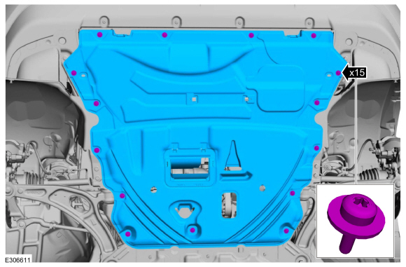
Remove the retainers and the underbody shield.
 |
-
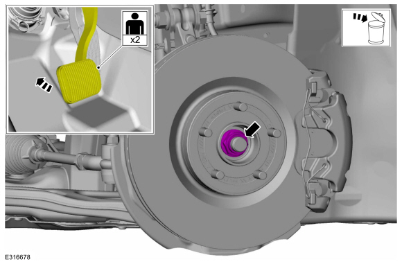
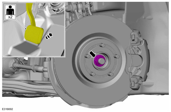
Remove and discard the wheel hub nut.
 |
-
-
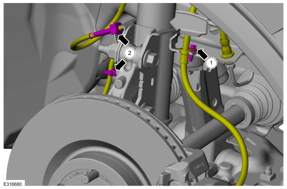
Remove the bolt and position aside the brake hose.
-
Unclip the 2 wire retainers and position aside the wheel speed sensor wiring harness.
-
Remove the bolt and position aside the brake hose.
 |
-
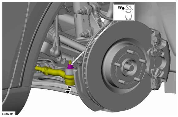
NOTICE: Do not use a hammer to separate the tie rod end from the wheel knuckle or damage to the wheel knuckle may result.
NOTICE: Use care when installing the tie rod separator or damage to the tie rod end boot may occur.
NOTE: Use the hex-holding feature to prevent turning of the stud while removing the tie rod end nut.
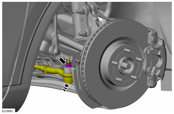
Remove and discard the tie rod end nut and separate the tie rod end from the wheel knuckle. Remove the halfshaft.
Use the General Equipment: Tie Rod End Remover
 |
-
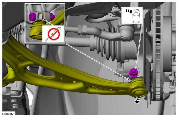
NOTICE: Do not use a prying device to open the slot in the knuckle to separate the lower ball joint from the knuckle assembly. Damage to the knuckle assembly may occur.
NOTICE: Do not use a prying device or separator fork between the ball joint and the wheel knuckle. Damage to the ball joint or ball joint seal may result. Only use the pry bar by inserting it into the lower arm body opening.
NOTICE: Use care when releasing the lower arm and wheel knuckle into the resting position or damage to the ball joint seal may occur.
NOTICE: Do not use power tools to remove or install the lower arm outboard nut. Damage to the ball joint or ball joint seal may occur.
NOTE: Use the TORX PLUS® holding feature to prevent the ball stud from turning while removing or installing the lower arm outboard nut. Torx® and TORX PLUS® is a registered trademark of Acument Intellectual Properties, LLC.
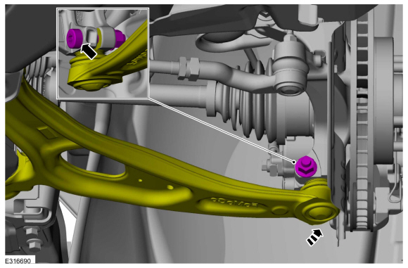
Remove and discard the ball joint pinch bolt and nut and separate the lower arm from the wheel knuckle.
 |
-
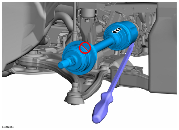
NOTICE: Do not bend the inner joint more than 18 degrees and the outer joint more than 45 degrees. Damage to the shaft will occur.
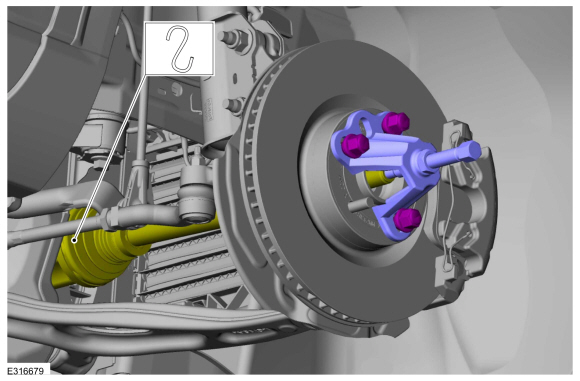
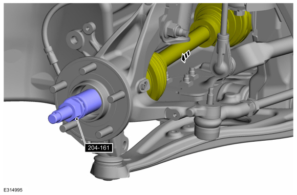
Using the special tool, press the halfshaft from the wheel bearing and hub. Support the halfshaft in a level position.
Use Special Service Tool: 205-D070 (D93P-1175-B) Remover, Front Wheel Hub.
 |
-
Remove the halfshaft.
 |
-
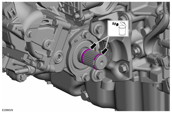
Remove and discard the circlip and O-ring seal from the intermediate shaft.
 |
Installation
-
Install the new circlip and O-ring seal on the intermediate shaft.
 |
-
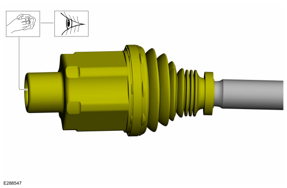
Clean and inspect the inboard end of the halfshaft.
 |
-
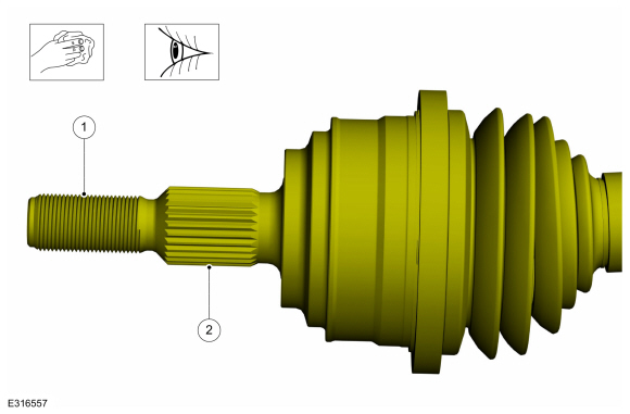
Clean and inspect the outer CV housing.
 |
-
Install the halfshaft.
 |
-
-
Insert halfshaft through the wheel bearing.
-
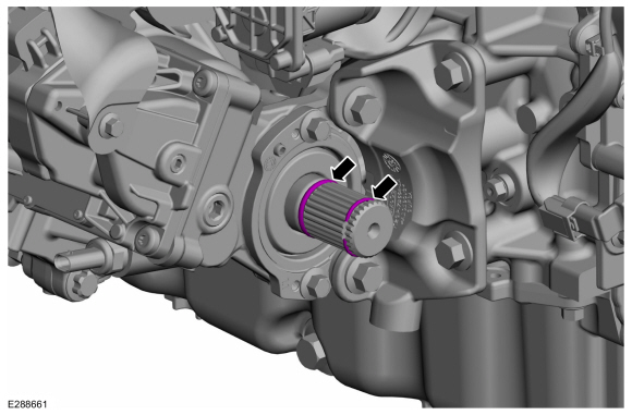
Using the special tool, seat the halfshaft splines in the wheel bearing.
Use Special Service Tool: 204-161 (T97P-1175-A) Installer, Halfshaft.
-
Insert halfshaft through the wheel bearing.
 |
-
NOTICE: Do not use power tools to remove or install the lower arm outboard nut. Damage to the ball joint or ball joint seal may occur.
NOTE: Use the TORX PLUS® holding feature to prevent the ball stud from turning while removing or installing the lower arm outboard nut. Torx® and TORX PLUS® is a registered trademark of Acument Intellectual Properties, LLC.
Position the ball joint into the wheel knuckle and install the new ball joint pinch bolt and nut.
Torque: 81 lb.ft (110 Nm)
 |
-
NOTICE: Use care when installing the tie rod separator or damage to the tie rod end boot may occur.
NOTE: Use the hex-holding feature to prevent turning of the stud while installing the tie rod end nut.
Attach the tie rod end to the wheel knuckle and install the new tie rod end nut.
Torque: 35 lb.ft (48 Nm)
 |
-
-
Position the brake hose and install the bolt.
Torque: 97 lb.in (11 Nm)
-
Position the wheel speed sensor wiring harness and clip the 2 wire retainers.
-
Position the brake hose and install the bolt.
|
-
NOTICE: Do not tighten the front wheel hub nut with the vehicle on the ground. The nut must be tightened to specification before the vehicle is lowered onto the wheels. Wheel bearing damage will occur if the wheel bearing is loaded with the weight of the vehicle applied.
NOTICE: Install and tighten the new wheel hub nut to specification in a continuous rotation. Always install a new wheel hub nut after loosening or when not tightened to specification in a continuous rotation or damage to the components may occur.
NOTE: Apply the brake to keep the halfshaft from rotating.
While an assistant applies the brake, install the new wheel hub nut.
Torque:
Stage 1: 74 lb.ft (100 Nm)
Stage 2: 60°
 |
-
Install the underbody shield and tighten the retainers.
Torque: 13 lb.in (1.5 Nm)
|
-
Install the wheel and tire.
Refer to: Wheel and Tire (204-04A Wheels and Tires, Removal and Installation).
 Removal and Installation - Front Halfshaft RH - 2.5L Duratec – Hybrid (121kW/164PS) (BG)
Special Tool(s) /
General Equipment
204-161
(T97P-1175-A)
Installer, HalfshaftTKIT-1997-LM2TKIT-1997-F/FM2TKIT-1997-FLM2
205-D070
(D93P-1175-B)
Remover, Front Wheel Hub
Tie Rod End Remover
Removal
Remove the wheel and tire...
 Removal and Installation - Intermediate Shaft
Materials
Name
Specification
Motorcraft® MERCON® ULV Automatic Transmission FluidXT-12-QULV
WSS-M2C949-A, MERCON® ULV
Removal
Remove the front halfshaft RH ...
Other information:
Ford Escape 2020-2026 Service Manual: Removal and Installation - Floor Console
Special Tool(s) / General Equipment Interior Trim Remover Removal NOTE: Removal steps in this procedure may contain installation details. Release the clips and remove the trim panel. Disconnect the electrical connectors...
Ford Escape 2020-2026 Service Manual: Diagnosis and Testing - Turbocharger Controls
Diagnostic Trouble Code (DTC) Chart Diagnostics in this manual assume a certain skill level and knowledge of Ford-specific diagnostic practices. REFER to: Diagnostic Methods (100-00 General Information, Description and Operation). Module DTC Description Action PCM P0234:00 Turbocharger/Supercharger 'A' Overboost Condition: No Sub Type Information GO to Pinpoint Test HN PCM ..
Categories
- Manuals Home
- 4th Generation Ford Escape Owners Manual
- 4th Generation Ford Escape Service Manual
- Removal and Installation - All-Wheel Drive (AWD) Module - 1.5L EcoBoost (132kW/180PS) – I3 (Y1)/2.0L EcoBoost (177kW/240PS) – MI4
- Opening and Closing the Hood
- Accessing the Trip Computer. Resetting the Trip Computer
- New on site
- Most important about car
Symbols Glossary
These are some of the symbols you may see on your vehicle.
 Air conditioning system