Ford Escape: Rear End Sheet Metal Repairs / Removal and Installation - Rear Side Member
Special Tool(s) /
General Equipment
| Resistance Spotwelding Equipment |
| 8 mm Drill Bit |
| MIG/MAG Welding Equipment |
| Spot Weld Drill Bit |
| Locking Pliers |
Materials
| Name |
Specification |
Seam Sealer
TA-2-B, 3M™ 08308, LORD Fusor® 803DTM |
-
|
Removal
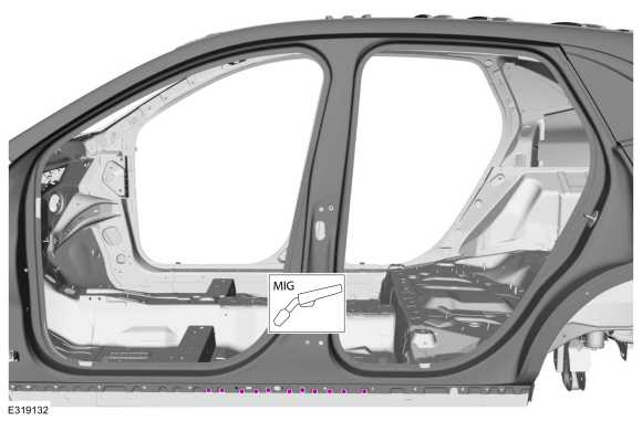
.jpg) WARNING:
Electric vehicles damaged by a crash may have compromised
high voltage safety systems and present a potential high voltage
electrical shock hazard. Exercise caution and wear appropriate Personal
Protective Equipment (PPE) safety gear, including high voltage safety
gloves and boots. Remove all metallic jewelry, including watches and
rings. Isolate the HV system as directed by the Ford Emergency Response
Guide for the vehicle. Failure to follow these instructions may result
in serious personal injury or death.
WARNING:
Electric vehicles damaged by a crash may have compromised
high voltage safety systems and present a potential high voltage
electrical shock hazard. Exercise caution and wear appropriate Personal
Protective Equipment (PPE) safety gear, including high voltage safety
gloves and boots. Remove all metallic jewelry, including watches and
rings. Isolate the HV system as directed by the Ford Emergency Response
Guide for the vehicle. Failure to follow these instructions may result
in serious personal injury or death.
NOTICE:
Battery electric vehicle (BEV), hybrid electric vehicle
(HEV) and plug-in hybrid electric vehicle (PHEV) contain a high-voltage
battery. Before cutting or welding near the high-voltage battery it must
be removed to avoid damage.
NOTE:
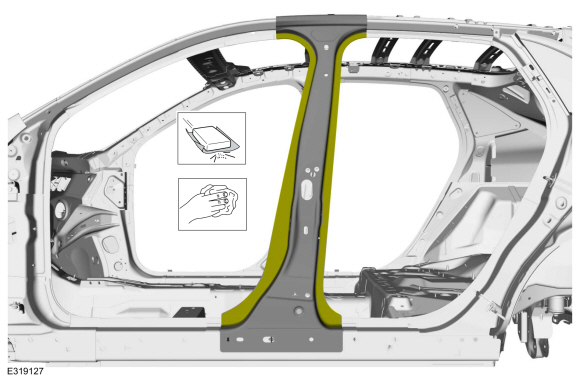
Left hand (LH) side shown, right hand (RH) side similar.
NOTE:
The rear side member is constructed of boron steel and may
not be sectioned. It must be replaced at factory seams only.
-
WARNING:
Before beginning any service procedure in this
manual, refer to health and safety warnings in section 100-00 General
Information. Failure to follow this instruction may result in serious
personal injury.
Refer to: Health and Safety Precautions (100-00 General Information, Description and Operation).
Refer to: High Voltage System Health and Safety Precautions - Overview (100-00 General Information, Description and Operation).
-
Depower the SRS .
Refer to: Supplemental Restraint System (SRS) Depowering (501-20B Supplemental Restraint System, General Procedures).
-
If Necessary:
Dimensionally restore the vehicle to pre-damage condition.
Refer to: Body and Frame (501-26 Body Repairs - Vehicle Specific Information and Tolerance Checks, Description and Operation).
-
Remove the rear subframe.
Refer to: Rear Subframe (502-00 Uni-Body, Subframe and Mounting System, Removal and Installation).
-
Remove the inner quarter panel.
Refer to: Inner Quarter Panel (501-30 Rear End Sheet Metal Repairs, Removal and Installation).
-
Remove the welds.
Use the General Equipment: Spot Weld Drill Bit
-
Remove the floor pan extension.
-
Remove the welds.
Use the General Equipment: Spot Weld Drill Bit
-
Remove the reinforcement.
-
Remove the welds.
Use the General Equipment: Spot Weld Drill Bit
-
Remove the welds.
Use the General Equipment: Spot Weld Drill Bit
-
Remove the welds.
Use the General Equipment: Spot Weld Drill Bit
-
Remove the rear side member.
Installation
WARNING:
Electric vehicles damaged by a crash may have compromised
high voltage safety systems and present a potential high voltage
electrical shock hazard. Exercise caution and wear appropriate Personal
Protective Equipment (PPE) safety gear, including high voltage safety
gloves and boots. Remove all metallic jewelry, including watches and
rings. Isolate the HV system as directed by the Ford Emergency Response
Guide for the vehicle. Failure to follow these instructions may result
in serious personal injury or death.
NOTICE:
Battery electric vehicle (BEV), hybrid electric vehicle
(HEV) and plug-in hybrid electric vehicle (PHEV) contain a high-voltage
battery. Before cutting or welding near the high-voltage battery it must
be removed to avoid damage.
NOTICE:
The high-voltage battery in a battery electric vehicle
(BEV), hybrid electric vehicle (HEV) or plug-in hybrid electric vehicle
(PHEV) can be affected and damaged by excessively high temperatures. The
temperature in some body shop paint booths can exceed 60° C (140° F).
Therefore, during refinishing operations, the paint booth temperature
must set at or below 60° C (140° F) with a bake time of 45 minutes or
less. Temperatures in excess of 60° C (140° F) or bake durations longer
than 45 minutes will require the high-voltage battery be removed from
the vehicle prior to placing in the paint booth.
NOTICE:
If refinishing cure temperatures exceed 60° C (140° F), the
charge port light ring on plug-in vehicles must be removed.
NOTE:
Factory welds may be substituted with resistance or metal
inert gas (MIG) plug welds. Resistance welds may not be placed directly
over original location. They must be placed adjacent to original
location and match factory welds in quantity. Metal inert gas (MIG) plug
welds must equal factory welds in both location and quantity.
NOTE:
Left hand (LH) side shown, right hand (RH) side similar.
NOTE:
The rear side member is constructed of boron steel and may
not be sectioned. It must be replaced at factory seams only.
-
WARNING:
Before beginning any service procedure in this
manual, refer to health and safety warnings in section 100-00 General
Information. Failure to follow this instruction may result in serious
personal injury.
Refer to: Health and Safety Precautions (100-00 General Information, Description and Operation).
Refer to: High Voltage System Health and Safety Precautions - Overview (100-00 General Information, Description and Operation).
-
Drill plug welds holes.
Use the General Equipment: 8 mm Drill Bit
-
Install, properly position and clamp the rear side member.
Use the General Equipment: Locking Pliers
-
Install the welds.
Use the General Equipment: Resistance Spotwelding Equipment
-
Install the welds.
Use the General Equipment: Resistance Spotwelding Equipment
-
Install the welds.
Use the General Equipment: MIG/MAG Welding Equipment
-
Drill plug weld holes.
Use the General Equipment: 8 mm Drill Bit
-
Install, properly position, clamp and weld the bracket.
Use the General Equipment: Locking Pliers
Use the General Equipment: MIG/MAG Welding Equipment
-
Drill plug weld holes.
Use the General Equipment: 8 mm Drill Bit
-
Install, properly position and clamp the reinforcement.
Use the General Equipment: Locking Pliers
-
Install the welds.
Use the General Equipment: Resistance Spotwelding Equipment
-
Install the welds.
Use the General Equipment: Resistance Spotwelding Equipment
-
Install the welds.
Use the General Equipment: MIG/MAG Welding Equipment
-
Drill plug weld holes.
Use the General Equipment: 8 mm Drill Bit
-
Install, properly position and clamp the floor pan extension.
Use the General Equipment: Locking Pliers
-
Install the welds.
Use the General Equipment: Resistance Spotwelding Equipment
-
Install the welds.
Use the General Equipment: MIG/MAG Welding Equipment
-
Dress all welds as necessary using typical metal finishing techniques.
-
Seam Sealing:
All seams must be sealed to production level.
Material: Seam Sealer
/ TA-2-B, 3M™ 08308, LORD Fusor® 803DTM
-
Seam Sealing:
All seams must be sealed to production level.
Material: Seam Sealer
/ TA-2-B, 3M™ 08308, LORD Fusor® 803DTM
-
Install the inner quarter panel.
Refer to: Inner Quarter Panel (501-30 Rear End Sheet Metal Repairs, Removal and Installation).
-
Refinish the entire repair using a Ford approved paint system.
-
Restore corrosion protection.
Refer to: Corrosion Prevention (501-25 Body Repairs - General Information, General Procedures).
-
Repower the SRS .
Refer to: Supplemental Restraint System (SRS) Repowering (501-20B Supplemental Restraint System, General Procedures).
Special Tool(s) /
General Equipment
Resistance Spotwelding Equipment
Spherical Cutter
Hot Air Gun
Air Body Saw
8 mm Drill Bit
MIG/MAG Welding Equipment
Spot Weld Drill Bit
Locking Pliers
Materials
Name
Specification
Seam SealerTA-2-B, 3M™ 08308, LORD Fusor® 803DTM
-
Flexible Foam Repair3M™ 08463, LORD Fusor® 121
-
..
Other information:
Item
Description
1
High voltage battery
Item
Description
1
High voltage battery cable
Item
Description
1
High voltage battery cover
Item
Description
1
BECM
Item
Description
1
High voltage battery junction box
Item
Description
1
DCDC and SOBDM fuse..
Once you select this option, the system
returns you to the main audio screen.
The current audio information appears on
the screen.
The following buttons are also available:
You can use the forward, reverse, pause or
play buttons to control the audio playback...
.jpg)
.jpg)
.jpg)
.jpg)
.jpg)
.jpg)
.jpg)
.jpg)
.jpg)
.jpg)
.jpg)
.jpg)
.jpg)
.jpg)
.jpg)
.jpg)
.jpg)
.jpg)
.jpg)
.jpg)
.jpg)
.jpg)
.jpg)
.jpg)

 Removal and Installation - Rear Wheelhouse Outer