Ford Escape: Rear Suspension / Removal and Installation - Spring
Special Tool(s) / General Equipment
| Vehicle/Axle Stands |
Removal
NOTICE: Suspension fasteners are critical parts that affect the performance of vital components and systems. Failure of these fasteners may result in major service expense. Use the same or equivalent parts if replacement is necessary. Do not use a replacement part of lesser quality or substitute design. Tighten fasteners as specified.
NOTE: Removal steps in this procedure may contain installation details.
-
Remove the wheel and tire.
Refer to: Wheel and Tire (204-04A Wheels and Tires, Removal and Installation).
-
NOTICE: The rear suspension height sensor must be disconnected from the lower control arm prior to servicing suspension components or damage to the suspension height sensor and/or the vehicle dynamic suspension system may occur. The sensor will need to be recalibrated after reassembly.
If equipped.
-
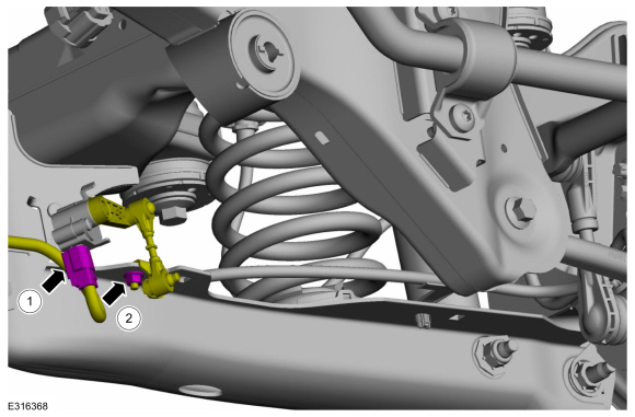
Disconnect the rear ride height sensor electrical connector.
-
Remove the rear height sensor arm bracket nut and position the rear height sensor arm bracket aside.
-
Disconnect the rear ride height sensor electrical connector.
 |
-
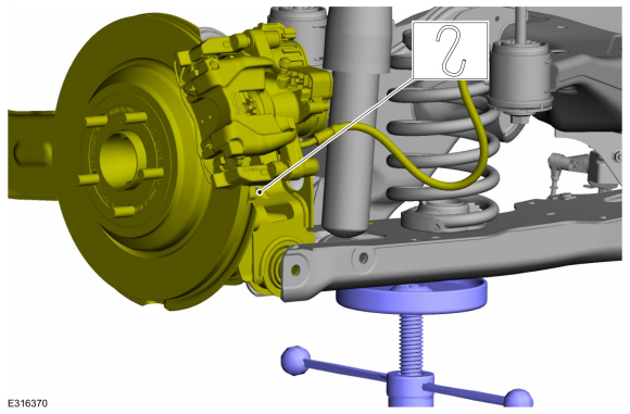
Using a suitable jackstand, support the rear lower arm at curb height.
Use the General Equipment: Vehicle/Axle Stands
 |
-
NOTICE: Do not attempt to jacking on the front control arm or rear control arm on any vehicle. Damage to control arms may occur.
NOTICE: Make sure that the insulator pads are correctly positioned to prevent direct contact with other components.
-
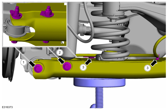
Remove and discard lower arm-to-wheel knuckle bolt and nut.
-
Remove and discard the rear shock absorber lower bolt and nut.
-
Unclip the rear wheel speed sensor wire harness retaining clips and position the harness aside.
-
Remove and discard lower arm-to-wheel knuckle bolt and nut.
 |
-
NOTICE: Never allow the knuckle to hang from the upper and lower control arms or damage to the ball joints can occur.
NOTE: Take care not to damage coating on suspension components.
Support the wheel knuckle assembly using mechanic's wire.
 |
-
NOTICE: Do not attempt to jacking on the front control arm or rear control arm on any vehicle. Damage to control arms may occur.
NOTICE: Make sure that the insulator pads are correctly positioned to prevent direct contact with other components.
-
Lower the suspension to release the spring compression.
-
Remove the spring by lowering the lower arm and position aside.
-
Lower the suspension to release the spring compression.
 |
Installation
NOTICE: Tighten the suspension fasteners with the weight of the vehicle on the wheels and tires or use a suitable jack to raise the suspension to curb height or damage to the bushings may occur.
-
Visual check.
Check the upper and lower spring seat for damage. Replace as necessary.
 |
-
NOTICE: Do not attempt to jacking on the front control arm or rear control arm on any vehicle. Damage to control arms may occur.
NOTICE: Make sure that the insulator pads are correctly positioned to prevent direct contact with other components.
-
NOTE: Hold spring in place while installing lower arm.
Install the spring into the upper and lower spring seat.
-
NOTE: Make sure that the spring is correctly located in the lower spring seat.
Visual check.
Align the spring in the lower spring seat.
-
Position the jackstand under the lower arm and raise the lower arm into position.
-
 |
-
NOTE: Make sure that the spring is correctly located in the upper spring seat.
Visual check.
Align the spring in the upper spring seat.
 |
-
NOTE: Only tighten the bolt and nut finger tight at this stage.
-
Position the lower arm to the wheel knuckle and install the new lower arm-to-wheel knuckle bolt and nut.
-
Install the new rear shock absorber lower bolt and nut.
-
Position the rear wheel speed sensor wire harness and clip the harness retaining clips into place.
-
Position the lower arm to the wheel knuckle and install the new lower arm-to-wheel knuckle bolt and nut.
 |
-
NOTICE: Tighten the suspension fasteners with the weight of the vehicle on the wheels and tires or use a suitable jack to raise the suspension to curb height or damage to the bushings may occur.
NOTE: Only tighten the nuts and bolts when the suspension is in the normal drive position.
-
Tighten the new lower arm-to-wheel knuckle bolt and nut.
Torque:
Stage 1: 81 lb.ft (110 Nm)
Stage 2: 120°
-
Tighten the new rear shock absorber lower bolt and nut.
Torque: 81 lb.ft (110 Nm)
-
Tighten the new lower arm-to-wheel knuckle bolt and nut.
 |
-
NOTICE: The rear suspension height sensor must be disconnected from the lower control arm prior to servicing suspension components or damage to the suspension height sensor and/or the vehicle dynamic suspension system may occur. The sensor will need to be recalibrated after reassembly.
If equipped.
-
Position the rear height sensor arm bracket and install the rear height sensor arm bracket nut.
Torque: 177 lb.in (20 Nm)
-
Connect the rear ride height sensor electrical connector.
-
Position the rear height sensor arm bracket and install the rear height sensor arm bracket nut.
 |
-
Install the wheel and tire.
Refer to: Wheel and Tire (204-04A Wheels and Tires, Removal and Installation).
-
Check and if necessary adjust rear toe.
Refer to: Rear Toe Adjustment (204-00 Suspension System - General Information, General Procedures).
-
NOTE: If equipped with dynamic suspension.
Calibrate the suspension system. Connect the scan tool and carry out the Ride Height Calibration routine. Follow the scan tool directions.
 Removal and Installation - Rear Stabilizer Bar Link
Removal
NOTICE:
Suspension fasteners are critical parts that affect the
performance of vital components and systems. Failure of these fasteners
may result in major service expense...
 Removal and Installation - Upper Arm
Special Tool(s) /
General Equipment
Vehicle/Axle Stands
Removal
NOTICE:
Suspension fasteners are critical parts that affect the
performance of vital components and systems...
Other information:
Ford Escape 2020-2026 Service Manual: Removal and Installation - Battery Monitoring Sensor
Removal NOTE: When the battery is disconnected and connected, some abnormal drive symptoms may occur while the vehicle relearns its adaptive strategy. The vehicle may need to be driven to allow the PCM to relearn the adaptive strategy values. NOTE: The battery monitoring sensor and the negative battery cable are serviced as an assembly...
Ford Escape 2020-2026 Owners Manual: Cooling System Capacity and Specification - 1.5L EcoBoost™
Use coolant that meets the defined specification. If you do not use coolant that meets the defined specification, it could result in: Component damage that your vehicle warranty does not cover. Reduced vehicle performance. Capacities Materials ..
Categories
- Manuals Home
- 4th Generation Ford Escape Owners Manual
- 4th Generation Ford Escape Service Manual
- Switching the Rear Window Wiper On and Off. Reverse Wipe
- Child Safety Locks
- Plug-In Hybrid Electric Vehicle Drive Modes
- New on site
- Most important about car
Vehicle Identification
Locating the Vehicle Identification Number
The vehicle identification number is on the left-hand side of the instrument panel.
