Ford Escape 2020-2026 Service Manual / Chassis / Steering System / Power Steering / Removal and Installation - Steering Gear Boot
Ford Escape: Power Steering / Removal and Installation - Steering Gear Boot
Special Tool(s) / General Equipment
| Boot Clamp Pliers |
Materials
| Name | Specification |
|---|---|
| Motorcraft® Premium Long-Life Grease XG-1-E1 |
ESA-M1C75-B |
Removal
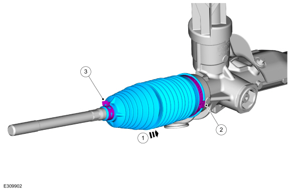
NOTE: Left hand (LH) side shown, right (RH hand side ) similar.
-
Remove the tie rod end.
Refer to: Tie Rod End (211-02 Power Steering, Removal and Installation).
-
NOTE: Count and record the number of turns required to remove the tie rod end jam nut for reference during installation.
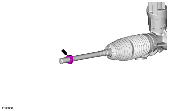
Remove the tie rod end jam nut.
 |
-
-
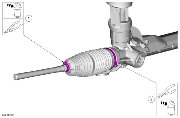
Remove and discard the outer steering gear boot clamp.
-
Remove and discard the inner steering gear boot clamp.
-
Remove and discard the outer steering gear boot clamp.
 |
-
Remove the steering gear boot.
 |
Installation
-
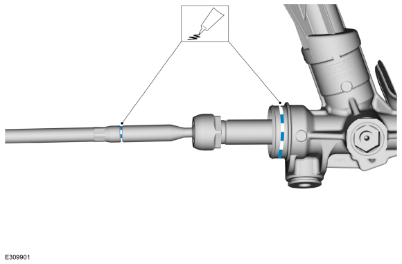
Apply the specified grease to the steering
gear-to-bellows boot mating surface and bellows boot groove on the inner
tie-rod.
Material: Motorcraft® Premium Long-Life Grease / XG-1-E1 (ESA-M1C75-B)
 |
-
NOTE: Make sure the steering gear bellows boot is positioned correctly over the steering gear housing bead and the groove in the inner tie rod.
-
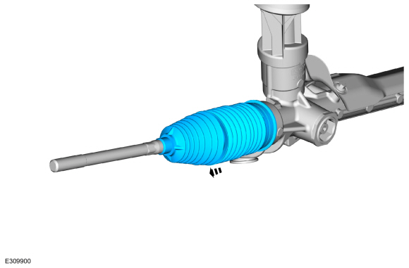
Install the steering gear boot.
-
Install the new inner steering gear boot clamp.
Use the General Equipment: Boot Clamp Pliers
-
Install the new outer steering gear boot clamp.
-
Install the steering gear boot.
 |
-
Install the tie rod end.
Refer to: Tie Rod End (211-02 Power Steering, Removal and Installation).
 Removal and Installation - Steering Gear
Removal
Remove the front subframe.
Refer to: Front Subframe (502-00 Uni-Body, Subframe and Mounting System, Removal and Installation).
Remove and discard the steering gear retainers...
 Removal and Installation - Tie Rod
Removal
NOTE:
If servicing the RH (right-hand) tie rod, both bellows boots must be removed.
Remove the steering gear boot.
Refer to: Steering Gear Boot (211-02 Power Steering, Removal and Installation)...
Other information:
Ford Escape 2020-2026 Service Manual: Removal and Installation - Front Door Check Arm
Removal NOTE: Removal steps in this procedure may contain installation details. NOTE: LH side shown, RH side similar. Open the door. Remove the check arm bolt. Torque: 18 lb.ft (25 Nm) Remove the front door trim panel...
Ford Escape 2020-2026 Service Manual: Diagnosis and Testing - Electronic Engine Controls
Diagnostic Trouble Code (DTC) Chart Diagnostics in this manual assume a certain skill level and knowledge of Ford-specific diagnostic practices. REFER to: Diagnostic Methods (100-00 General Information, Description and Operation). Module DTC Description Action PCM P0602:00 Powertrain Control Module Programming Error: No Sub Type Information GO to Pinpoint Test QA PCM P0604..
Categories
- Manuals Home
- 4th Generation Ford Escape Owners Manual
- 4th Generation Ford Escape Service Manual
- Removal and Installation - All-Wheel Drive (AWD) Module - 1.5L EcoBoost (132kW/180PS) – I3 (Y1)/2.0L EcoBoost (177kW/240PS) – MI4
- Plug-In Hybrid Electric Vehicle Drive Modes
- All-Wheel Drive
- New on site
- Most important about car
Under Hood Fuse Box
Locating the Under Hood Fuse Box

Accessing the Under Hood Fuse Box

Copyright © 2026 www.fordescape4.com